ISO 9001, ISO 14001, ISO 45001 und IECQ QC080000
 Über 15 Jahre Erfahrung
 KOSTENLOSE Muster zur Sicherstellung der Produktzufriedenheit
 Schnelle Abwicklung: Massenproduktion in 15 - 20 Tagen abgeschlossen

When you search for a spring test probe, you’ll often get pogo pins. Search for pogo pins, and you’ll get test probes. The same component photograph shows up under different names on the same page. That confusion costs real time when you’re specifying parts for a fixture, and it usually surfaces during bring-up rather than at the quoting stage.
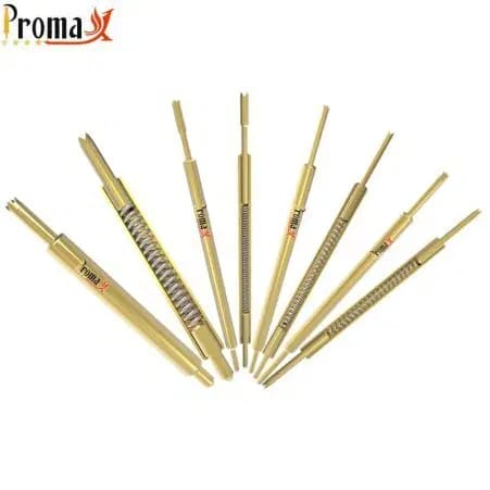
Both belong to the same family of spring-loaded contacts. What matters is the job each part was built to do. Engineers already scoping a build can compare spring test probes for PCB testing against the fixture in front of them.
What Separates a Spring Test Probe From a Pogo Pin?
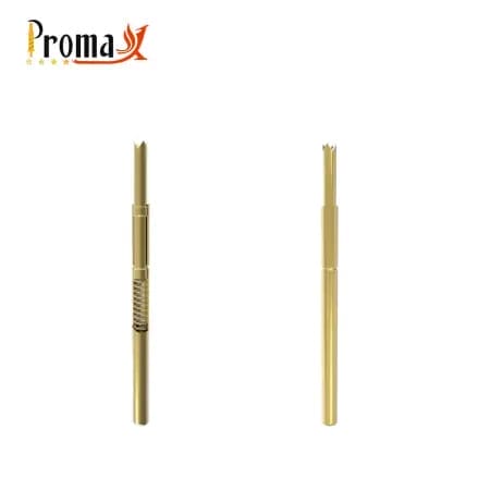
A spring test probe is a pogo pin engineered for repeated test contact. It carries the same plunger, barrel, and spring assembly. Tip geometry, spring force, and expected service life match a test method rather than a finished product. It lives in a fixture as a replaceable part. A general-purpose pogo pin lives inside a device and stays there for the life of the product.
Both parts are built the same way. A plunger rides inside a barrel, a spring pushes it out, and current passes through the assembly when the tip lands on a target. Pull one of each apart on the bench, and you’d struggle to tell them apart by construction alone.
Service life and purchasing model are where they diverge. A test probe is a consumable. It sits in a fixture, lands on a test point thousands of times, and gets replaced when contact starts drifting. A product pogo pin is designed in. It goes inside a charging cradle or a docking connector and stays there.
The table below sets the two side by side across the decisions that actually differ between them. Specific numbers are omitted because every figure moves with part design and application.
| Dimension | Spring test probe | Product pogo pin | Why it matters |
|---|---|---|---|
| Where it lives | In a fixture or test head, mounted for removal | Inside the finished device | Sets whether you’re buying a consumable or a designed-in part |
| Job | Repeated temporary contact against a test point | Docking or continuous contact in service | Defines the wear model you design around |
| Tip geometry | Chosen for the target and its surface condition | Usually flat or rounded against a mating pad | A mismatched tip reads as a failed board, not a bad probe |
| Mounting | Receptacle-mounted so probes swap out | Soldered, pressed, or housed | Determines downtime when contacts wear |
| Force specification | Set against the fixture’s total force budget | Set for contact stability in the product | Drives plate design and board support |
| Service expectation | Consumable, tracked and replaced in batches | Sized to the product’s service life | Changes the qualification questions you ask a supplier |
| Plating rationale | Tuned for wear and repeated cleaning | Tuned for the service environment | Governs how contact behaves over time, not on day one |
Why the two terms get used interchangeably
The naming came out of the test industry and spread from there. Spring probe, contact probe, pogo pin, and test pin all describe the same mechanism. No standards body has ever settled on a single term, so suppliers use whichever one their customers search for.
Retail listings make it worse. One item gets tagged with all four names to surface on every query. A search for probes then returns product pogo pins, and the reverse happens too. Specifying by name alone gets you a part that looks right but behaves wrong. You find out during fixture bring-up.
What changes when the pin is a consumable
Cost per board, not unit price, is what you’re really buying. A probe that costs less but needs replacing twice as often works out more expensive across a production run. The downtime while you swap probes usually costs more than the parts themselves.
Receptacles exist for that reason. Probes press into a receptacle that stays soldered or wired into the plate, so a worn probe pulls out without anyone touching the wiring. The questions you put to a supplier also change. You’re asking how the part degrades under your duty cycle, not just how it measures on day one.
What Do ICT Fixtures Demand From a Probe?
In-Circuit Test (ICT) puts the probe against a populated board, which is a harder target than bare copper. Test points are often solder-coated pads and sometimes component leads, and they arrive at the fixture carrying flux residue and light oxide. The tip has to reach clean metal through that layer without damaging the pad underneath.
The table below maps one set of requirements across all three test methods.
| Requirement | In-circuit test | Flying probe | Bed-of-nails grid |
|---|---|---|---|
| Probe population | Hundreds, landing simultaneously | A handful, working sequentially | Dense array across the full board |
| What it touches | Loaded board, pads and component leads | Pads, vias, and awkward access points | Bare board copper and test points |
| Where wear shows | Spread across the fixture, uneven by zone | Concentrated on very few tips | Spread, but high in dense zones |
| Force behavior | Per-probe force sums into a fixture load | Per-probe force applied point by point | Distribution across the plate is the design problem |
| Setup cost model | Custom fixture per board design | No fixture, slower per board | Custom plate stack per board design |
| Serviceability | Batch replacement on pass-rate drift | Frequent replacement of few parts | Batch replacement, alignment rechecked |
| Best suited to | Volume production of a stable design | Prototypes, low volume, access problems | Bare-board verification at volume |
The test regime answers to IPC-9252B, which sets continuity and isolation thresholds by product class rather than by probe type. Worth reading before you finalize a fixture spec — the class your customer builds to determines how much margin you need in the contact path. IPC’s technical material on electrical test conditions covers the practical side of applying those classes.
The force budget across a full fixture
Per-probe force sounds trivial until you multiply it out. A few dozen grams at each contact, across several hundred contacts, adds up fast. The plate stack and the press both have to carry that total load. Fixture designers work to a combined figure, not a per-part one.
Get it wrong in either direction and the fixture tells you soon enough. Too little force and contact goes intermittent, which reads on the report as a failed board rather than a fixture problem. Too much and you mark pads or bow the board under the plate.
The figure that works isn’t a property of the probe alone. It comes down to probe count, plate design, board support, and the surface you’re landing on – all considered together.
Serviceability and replacement cadence
Pass rates drift before probes fail outright. If yield on a stable product starts sliding and nothing changes on the line, the probes are the first thing worth checking.
Replace them in batches. Swapping one probe at a time leaves mixed wear across the fixture, and mixed contact force produces position-dependent failures that are difficult to debug.
How Do Flying Probe Systems Change the Requirements?
Different economics entirely. A handful of probes do the work of a whole fixture, moving from point to point under machine control. Nothing gets built up front, and the test cycle runs much slower per board. That trade-off is why flying probe suits prototypes, low-volume runs, and boards where access is awkward.
For the probe itself, two things change. Wear concentrates instead of spreading, and no plate holds alignment. Wikipedia covers the fixtureless in-circuit test approach behind flying probe systems for those who want the background.
Wear and cycle life in a sequentially probed system
Every test point on the board passes through the same handful of tips. A bed-of-nails fixture spreads a day of work across hundreds of contacts. A flying prober puts all of it through four or fewer. Cycle counts per probe climb accordingly.
Cycle life ratings vary widely between probe series. That spread comes from tip geometry, plating stack, barrel diameter, and how hard the duty cycle runs. Treat a published figure as a comparison within one supplier’s range rather than a number that carries across to another.
Replacement frequency per tip runs higher than for any individual probe in a large fixture. Total probe spend usually runs lower, since you’re maintaining a handful of parts instead of a plate full of them.
Positional accuracy and tip requirements without a fixture
No plate means the machine’s own accuracy and the tip geometry carry the full positional burden. A fixture forgives small errors because the plate holds every probe where the drawing says it goes. A flying prober has nothing doing that job.
One board might present fine-pitch pads, vias, and component leads in the same net list. The tip has to work across all of them, which usually pushes toward a geometry that performs adequately everywhere rather than optimally on one target. A mismatch shows up as a false failure, and false failures on a prototype eat debug hours nobody budgeted.
Brauchen Sie schnell Pogo-Pins? Sprich mit einem Ingenieur
Erhalten Sie ein individuelles Angebot, passende Spezifikationen und Fertigungsberatung – ohne Ihr Projekt zu verlangsamen.
- ISO 9001 / 14001 / 45001 + IECQ QC080000
- Über 15 Jahre Erfahrung
- Kostenlose Muster
- Serienfertigung in 15–20 Tagen
What Makes Bed-of-Nails Fixtures Different?

Density is the defining constraint. Every test point on the board gets a contact; they all land at once, and the plate stack is custom to that board design. Bare-board work has the probe touching copper and plated through-holes rather than solder, which shifts both tip selection and cleaning cadence.
Repeatability across the array is a system property. Alignment through the plate stack, board support underneath, force distribution across the grid, and the consistency of the probes themselves all feed into it. A fixture with hundreds of contacts only behaves if the probes behave alike, and that’s a manufacturing question rather than a specification question.
Consistency at that scale is what our production process is built around. Promax Pogo-Pin holds mass production yield above 99%, which matters here for a specific reason. A fixture is only as repeatable as its least consistent contact. Batch-to-batch variation shows up as position-dependent failures long before any single probe fails outright. We manufacture the probes that go into these fixtures. Building the fixture itself stays with you or your fixture house.
How Do You Choose Tip Style and Spring Force?
Tip geometry is the first decision, and what the tip has to land on drives it – not the probe’s other specifications. Surface condition matters as much as the shape of the target. A pad that arrives clean and a pad that arrives under flux want different tips.
The table below pairs each common geometry with the targets it handles well and the trade-off that comes with it.
| Tip style | Lands well on | Watch for |
|---|---|---|
| Crown | Solder-coated pads, through-hole test points, and general-purpose fixtures where surface conditions vary | Multiple points help on flux and oxide, though they also collect debris and need a cleaning routine |
| Spear or needle | Plated pads and vias where a small mark is acceptable | Concentrated force marks the surface and wears the point, so replacement cadence tightens |
| Serrated or waffle | Flat contaminated surfaces, terminals, and pins | Debris sits in the pattern, and cleaning becomes part of the maintenance plan |
| Flat | Solder bumps, posts, and anywhere marking is unwelcome | Less able to reach clean metal through a poor surface |
| Concave or cup | Protruding leads, terminals, and long wire ends that need guiding | Alignment matters more, since the shape is doing the capture |
| Chisel | Moderately corroded surfaces where a blade edge helps | Contact angle affects consistency, so fixture alignment carries more weight |
Crown tips
Four or more points arranged in a circle give you redundancy. If one point lands on flux or oxide, the others still make contact. Crown tips end up as the default choice in general-purpose fixtures for that reason.
They suit solder-coated pads and through-hole test points. The pattern does collect debris over time, so build a cleaning routine into fixture maintenance rather than waiting for pass rates to prompt it.
Spear and needle tips
A single point concentrates force into a small area, which helps on plated pads and vias where a witness mark is acceptable. Fine-pitch work often leaves no alternative.
Wear and marking are the trade-off. The point wears faster than a distributed geometry, and the replacement cadence tightens to match. Anywhere cosmetic marks matter, this tip isn’t the right choice.
Serrated and waffle tips
Many small points across a flat face let the tip find clean metal on a contaminated or lightly oxidized surface. Flat terminals and pins are the natural targets.
Debris collects in the pattern rather than wiping off. Cleaning shifts from a good habit to a scheduled part of the maintenance plan.
Flat and concave tips
Flat faces are the gentle option. They suit solder bumps and posts, and any target where marking is unacceptable. Concave and cup shapes do a different job: they capture protruding leads, terminals, and long wire ends so they seat consistently.
Both are less able to break through a poor surface. If boards arrive with contamination, plan on cleaning them first or select a tip with more bite.
Chisel tips
A blade edge concentrates force along a line rather than at a point, which helps on moderately corroded or oxidized surfaces. The contact area sits between a spear and a flat.
Contact angle matters more than it does with symmetrical geometries, so fixture alignment carries more weight when chisel tips are in use. The edge also wears unevenly under lateral load, which makes replacement a fixture-level review rather than a per-probe one.
Matching spring force, plating, pitch, and cycle life to the job
Spring force follows the tip and the target. A tip that has to break through a surface layer needs more force behind it, while a delicate target needs less. The total across the fixture still has to stay within what the plate and press can carry. Published force ranges vary considerably between probe series, so compare within a supplier’s range rather than across suppliers.
Plating is a wear and oxidation decision rather than a ranking of materials. Gold over Nickel is the common stack where probes see repeated cleaning cycles. Thickness and underplate affect long-term performance as much as the material name does. Where contact resistance drives the specification, our guide on pogo pin contact resistance covers it properly.
Pitch follows the board. How tight a supplier can go depends on barrel diameter, plunger design, and their own process capability. Cycle life works the same way—it’s a duty question rather than a headline figure.
Custom work is where a catalog stops being useful. At Promax, we build tip geometries and plating stacks to the customer’s drawing. What’s achievable on any given dimension depends on the pin design, the material, the finished size, and the process behind it.
Pick the test method first, then the tip, then the spring force. Most probe selection problems trace back to specifying from a catalog page rather than from the fixture, and the fixture is what decides. Get the method right and the specifications narrow to a short list.
Send us your test point map and the surface finish you’re working with. Our engineers respond within 1–3 days with a recommendation, and samples ship within two weeks so you can qualify the tip before the plate gets cut.
FAQs on Spring Test Probe vs Pogo Pin
Can I use the same probe part number in an ICT fixture and a flying prober?
Rarely. Probes for grid fixtures are built around receptacle mounting and a shared force budget. Prober tips mount into the machine’s own head and take far higher cycle counts individually. The mechanism is the same, but mounting and duty assumptions differ enough that most part numbers suit one context or the other.
How do I qualify a probe before committing to a full fixture build?
Run samples against a known-good board before the plate is cut. Mount candidate geometries in a small jig and run a few hundred cycles. That tells you whether the tip reaches clean metal on your actual surface finish. Qualifying at the sample stage costs days. Discovering the problem after the plate is drilled costs weeks.
Do I need receptacles, or can probes mount directly into the plate?
Receptacles are standard practice for anything you plan to service. The receptacle stays wired into the plate while the probe pulls out, so replacement takes seconds and leaves the wiring untouched. Direct mounting saves height and cost, which suits low-cycle jigs and one-off builds where you’d scrap the plate before servicing it. Our test probe range covers receptacle-compatible options if you need to compare mounting formats.
When should I replace probes rather than clean them?
Clean first, then replace when cleaning stops restoring the pass rate. Debris on the tip responds to cleaning. A worn tip or a tired spring does not. If pass rates recover after a clean but slide faster each time, the probes are near the end of life.
What is the minimum order for custom test probes?
Free samples cover qualification. Production minimums depend on the tip geometry and plating combination you settle on. Standard geometries in common platings run lower than fully custom tooling. Contact for details on a specific combination.
Zurück nach oben Spring Test Probe vs Pogo Pin: Choosing by Test Method
Brauchen Sie schnell Pogo-Pins? Sprich mit einem Ingenieur
Erhalten Sie ein individuelles Angebot, passende Spezifikationen und Fertigungsberatung – ohne Ihr Projekt zu verlangsamen.
- ISO 9001 / 14001 / 45001 + IECQ QC080000
- Über 15 Jahre Erfahrung
- Kostenlose Muster
- Serienfertigung in 15–20 Tagen