ISO 9001, ISO 14001, ISO 45001 e IECQ QC080000
 Fabricando desde 2014
 Muestras GRATUITAS para garantizar la satisfacción del producto
 Giro rápido: Producción en masa completa en 15 - 20 días

Dos pogo pins fabricados según la misma ficha técnica pueden diferir en su vida útil real en años. La diferencia está en cómo cada uno gestiona la relajación del resorte, el desgaste del chapado y los restos con el tiempo.
La diferencia no es cuestión de suerte. Depende de cómo se especifica un pin y de lo honestos que son los datos de su ficha técnica cuando la pieza queda sellada dentro de una carcasa real. Acierta con la corriente nominal, el chapado y las especificaciones del resorte del pogo pin para las condiciones reales de funcionamiento, y la pieza alcanzará su vida útil nominal. Fállalos, y fallará antes de tiempo.
Las secciones siguientes explican qué determina esa especificación y qué significa la vida útil más allá de la ficha técnica. También repasan los seis patrones de fallo que conviene conocer antes de una devolución en campo.
¿Cómo se mide la fiabilidad de un pogo pin?
La fiabilidad de un pogo pin se reduce a tres parámetros vinculados: una resistencia de contacto estable a lo largo de la vida útil nominal, la propia vida útil nominal y la capacidad de corriente adaptada al entorno de trabajo. Los pogo pins estándar suelen estar especificados para 100.000 ciclos de conexión o más. Los modos de fallo más habituales son la fatiga del resorte, el desgaste del chapado, la corrosión por fretting, la entrada de partículas, la sobrecorriente y la pérdida de fuerza del resorte.
Estos tres parámetros no se mueven de forma independiente. La resistencia de contacto depende de cómo aguanta el chapado, y el estado del chapado depende de cuántos ciclos ha visto ya la pieza. La precisión en un pogo pin no es realmente una propiedad del pin. Es lo que producen en conjunto un resorte, una geometría de cuerpo, una especificación de chapado y un proceso de fabricación bien ajustados.
Esas expectativas no dejan de crecer a medida que los pogo pins se incorporan a aplicaciones de mayor exigencia. Las plataformas de vehículo eléctrico (VE) y la electrónica similar están entre los segmentos de crecimiento más rápido en el sector de los conectores ahora mismo.
Hay dos marcos de prueba que aparecen cuando los ingenieros verifican ese sistema. IEC 60512 abarca la resistencia de contacto y las pruebas de continuidad. MIL-STD-1344 es el estándar militar estadounidense anterior que estableció muchos de los métodos de ensayo de conectores que todavía se referencian en el sector hoy en día. Si un proveedor no puede aportar datos de vida útil frente a algo de esa familia, merece la pena investigarlo antes de comprometerte con un diseño.
Corriente nominal de un pogo pin: ¿qué la determina y cómo especificarla?
La corriente nominal es el límite de amperaje continuo que puede soportar un pin antes de calentarse más de lo que sus materiales toleran. Suele ser el primer dato que comprueba un ingeniero. También es el más fácil de equivocar, ya que dos pines casi idénticos en una ficha técnica pueden soportar cargas muy distintas.
¿Qué afecta a la corriente nominal?
El diámetro del pin es el que hace la mayor parte del trabajo. Una sección transversal más ancha da a la corriente un camino más fácil. Por eso los pines SMD estándar suelen soportar unos pocos amperios. Los diseños específicos de alta corriente llegan más lejos, hasta unos 40 A en algunas configuraciones.
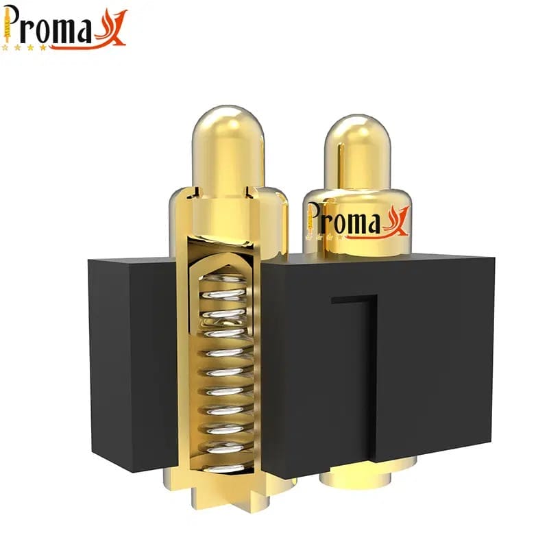
Lo consiguen con un cuerpo más grueso y un manguito conductor de corriente que lleva la alimentación alrededor del resorte. Esa cifra es un ejemplo de capacidad, no una especificación fija que alcance todo pin de alta corriente. El límite real depende del diámetro del pin, el chapado y la capacidad de proceso de cada fabricante.
El chapado importa casi tanto. El oro presenta una resistencia de contacto menor que el níquel, por lo que una interfaz chapada en oro mueve la corriente de forma más eficiente donde pasa del pin a la almohadilla. El propio resorte suele ser el eslabón de mayor resistencia de la cadena. Por eso los diseños de alta corriente lo rodean en lugar de pasar por él.
La superficie de contacto entre el émbolo y el cuerpo también importa. Es la superficie que realmente conduce. Se reduce sin que se note si se desgasta o acumula suciedad, incluso cuando la pieza parece estar bien por fuera.
Cómo aplicar el derrateo por temperatura
La temperatura ambiente se come ese techo. A medida que el aire circundante se calienta, el pin tiene menos margen térmico antes de entrar en territorio inseguro. La corriente de trabajo segura baja, aunque la pieza en sí no haya cambiado.
La tabla siguiente muestra la forma de una curva de derating que podría publicar un fabricante. Tómala como un patrón previsible, no como un número que copiar. Las curvas reales varían según la geometría del pin, el chapado y la aleación del resorte.
| Temperatura ambiente | Derating recomendado | Guía práctica |
|---|---|---|
| ≤25 °C | 100% de la corriente nominal | Base de la ficha técnica; se asume convección al aire libre |
| 40 °C | ~90% de la corriente nominal | Habitual en envolventes industriales ventiladas |
| 60 °C | ~80% de la corriente nominal | Habitual en electrónica de consumo cerrada y wearables |
| 85 °C | ~65% de la corriente nominal | Límite superior estándar; verifica la temperatura nominal de la aleación del resorte |
| 105 °C | ~50% de la corriente nominal | Rango ampliado; requiere una aleación de resorte resistente al calor y un chapado más grueso |
| 125 °C | ~40% de la corriente nominal (verificar) | Máximo para la mayoría de diseños de pogo pin; consulta al fabricante para su validación |
Valores representativos para diseños de pogo pin estándar. Las curvas de derrateo reales varían según el fabricante, la geometría del pin y el chapado. Solicita a tu proveedor los datos de ensayos térmicos para tu entorno de trabajo concreto.
Una regla práctica razonable: especifica una corriente nominal con un margen del 20-30% por encima de lo que tu dispositivo consume realmente en funcionamiento continuo. Un pin dimensionado al límite de tu carga, dentro de una carcasa cerrada con ventilación limitada, es buscarse problemas. Las corrientes nominales de las fichas técnicas casi siempre asumen convección al aire libre, que rara vez es lo que ofrece un wearable o una carcasa médica sellada.
Si tu aplicación trabaja en caliente o va encerrada, pide a tu fabricante datos reales de ensayos térmicos en lugar de fiarte de la cifra de portada. La misma lógica de corriente frente a calor aparece en estándares de nivel de placa como IPC-2221, que rigen la capacidad de corriente de las pistas de la placa de circuito impreso (PCB).
Vida útil del pogo pin: qué significan realmente más de 100.000 ciclos
Los pogo pins estándar suelen tener una vida útil de 100.000 ciclos de conexión o más. Esa base se ha convertido en un estándar en el sector. Sin embargo, no es una regla fija que todas las piezas cumplan. Es un ejemplo de capacidad que depende del material del resorte, el espesor del chapado, el tamaño del pin y los controles de proceso del fabricante.
Opta por un chapado en oro más grueso, una aleación de resorte de alta calidad y un control de proceso más estricto. La cifra se multiplica varias veces, hasta las seis o siete cifras. Lo que cambia entre esos niveles no es el diseño básico del pin. Es el margen de material y de proceso que el fabricante ha incorporado.
La vida útil mide algo concreto: el punto en el que la resistencia de contacto cruza un umbral definido, normalmente un aumento de resistencia admisible. Si se cruza esa línea, el pin ha fallado funcionalmente, aunque siga moviéndose físicamente.
La contaminación, la compresión excesiva, las cargas laterales y el calor sostenido reducen la vida útil real por debajo de la cifra de la ficha técnica. Esa diferencia suele situarse entre la mitad y las tres cuartas partes del valor nominal. Conviene recordarlo al comparar un valor nominal con el periodo de garantía de un producto.
Un wearable que se carga una vez al día durante tres años necesita algo más de 1.000 ciclos. Un utillaje de test de producción que realiza 500 ciclos al día durante dos años necesita algo del orden de seis cifras. Ajusta la especificación al trabajo, con margen, en lugar de ir a por el número más alto de la ficha técnica. Nuestro guía de diseño de pogo pins explica cómo interactúa ese margen con el resto del diseño.
Modos de fallo de los pogo pins

Todo pogo pin acaba fallando. Es cierto para cualquier contacto mecánico, y ningún chapado ni aleación de resorte lo cambia. Lo que separa un buen diseño de un problema de devoluciones en campo es el momento. Un fallo predecible según lo previsto es una cosa. Un fallo prematuro, porque algo del diseño o del entorno no se tuvo en cuenta, es otra.
Los seis patrones siguientes cubren casi todo lo que aparece en la práctica. Cada uno se remonta a algo concreto que puedes especificar antes de que se convierta en una devolución de campo.
Fatiga del resorte
La compresión repetida más allá del límite elástico del resorte reduce poco a poco la fuerza que este puede ejercer. Lo mismo ocurre con el funcionamiento continuado a alta temperatura, que reblandece el temple del resorte. El síntoma es una presión de contacto inconsistente.
La solución está sobre todo en la especificación. Incluye un margen por encima de la fuerza mínima que necesita tu aplicación y mantente dentro de la carrera de trabajo nominal del fabricante. Nuestra guía de diseño explica cómo especificar la carrera del contacto desde el principio.
Desgaste del chapado
Cada ciclo de conexión implica una pequeña acción de frotamiento en la interfaz de contacto, y ese frotamiento desgasta lentamente el chapado. El oro se desgasta hasta el subchapado de níquel tras suficientes ciclos. Una vez que se traspasa ese límite, la resistencia de contacto sube rápidamente.
La prevención es sencilla en concepto. Ajusta el espesor del chapado al requisito de vida útil en lugar de usar un valor estándar por defecto. Confirma el espesor real con tu fabricante, en vez de dar por hecho que “chapado en oro” ya lo dice todo.
Corrosión por fretting
Las microvibraciones en la interfaz de contacto, más pequeñas de lo que percibirías a simple vista, hacen que se formen y se acumulen diminutas partículas de óxido. Esas partículas aíslan gradualmente la superficie de contacto. Lo que obtienes es una deriva de la resistencia que parece intermitente y empeora poco a poco.
Suficiente fuerza del resorte para mantener un contacto firme es la primera defensa. Combínalo con un diseño de contacto deslizante que arrastre la capa de óxido en cada conexión, y se mantiene a raya. Investigación del IEEE sobre corrosión por fretting aborda este mecanismo con más detalle.
Entrada de residuos y contaminación
El polvo, los residuos de flux y otras partículas pueden colarse en el cuerpo e interferir con el recorrido del émbolo. Según la cantidad que entre, verás desde un émbolo que se mueve con dificultad hasta uno totalmente bloqueado. La resistencia de contacto sube y aparecen circuitos abiertos por el camino.
Las carcasas con un grado de protección IP ayudan. También lo hace una interfaz de acoplamiento diseñada para minimizar la entrada de partículas. Ambas son contramedidas estándar para cualquier elemento que funcione fuera de un entorno limpio y controlado.
Sobreintensidad y arco eléctrico
Trabajar por encima de la corriente nominal, sobre todo durante una conexión en caliente o un pico de corriente de irrupción, provoca picaduras localizadas y transferencia de material en la superficie de contacto. En los peores casos, se produce una fusión localizada y un aumento permanente de la resistencia que no se recupera. Hay tres cosas que ayudan a evitarlo casi por completo.
Especifica la corriente nominal con un margen por encima de tu consumo máximo real. Utiliza circuitos de arranque suave donde la corriente de irrupción sea un riesgo conocido y evita la conexión en caliente bajo carga siempre que sea posible.
Conjunto de resortes y fluencia
Este se manifiesta de forma distinta a los demás. Se desarrolla durante una compresión estática prolongada a temperaturas elevadas, no durante ciclos de conexión activos. Un pin mantenido en estado comprimido durante meses dentro de una carcasa caliente puede deformarse de forma permanente, aunque nunca se haya sometido a ciclos especialmente intensos.
La prevención consiste en elegir un material de resorte apto para tu temperatura de trabajo real. Evita los diseños que dejan el pin comprimido de forma permanente cuando no es necesario.
¿Necesitas pines pogo rápido? Habla con un ingeniero
Get a custom quote, spec matching, and manufacturing guidance without slowing down your project.
- ISO 9001 / 14001 / 45001+ IECQ QC080000
- 15+ años de experiencia
- Muestras gratis
- Producción en masa en 15–20 días
Modos de fallo de un vistazo
Los seis patrones anteriores se resumen a continuación para consulta rápida.
| Modo de fallo | Causa raíz | Síntoma | Prevención / Guía de especificaciones |
|---|---|---|---|
| Fatiga del resorte | Sobrecompresión repetida; pérdida de temple del resorte a alta temperatura | Fuerza del resorte reducida; contacto intermitente | Especifica la fuerza del resorte con margen; mantente dentro de los límites de carrera de trabajo |
| Desgaste del chapado | Abrasión mecánica durante los ciclos de conexión | Aumento de la resistencia de contacto; exposición del metal base | Ajusta el grosor del chapado en oro al requisito de vida útil |
| Corrosión por fretting | Microvibración en la interfaz de contacto | Deriva intermitente de la resistencia | Fuerza del resorte adecuada; diseño de contacto con efecto de barrido |
| Entrada de residuos | Entrada de polvo, flujo y partículas en el cuerpo | Émbolo atascado; circuitos abiertos | Carcasa con clasificación IP; diseño de interfaz de conexión estanca |
| Sobrecorriente y arco eléctrico | Funcionamiento por encima de la corriente nominal; conexión en caliente | Picado de los contactos; aumento permanente de la resistencia | Derrateo de corriente con margen; circuitos de arranque suave; evita la conexión en caliente bajo carga |
| Conjunto de resortes y fluencia | Compresión estática prolongada a alta temperatura | Deformación permanente del resorte; menor presión de contacto | Material del resorte con clasificación térmica; evita la compresión permanente |
Patrones de fallo representativos basados en una construcción estándar de pogo pin. Los umbrales reales de fallo varían según el diseño, el material y las condiciones de la aplicación.
Desventajas de los pogo pins: cuándo no usarlos
Los pogo pins no son el conector adecuado para todos los trabajos, y fingir lo contrario no ayuda a nadie. Merece la pena nombrar directamente cuatro situaciones.
Los entornos de alta vibración sin una carcasa bien diseñada son el primero. Los contactos con resorte pueden perder el contacto momentáneamente bajo impactos severos si la carcasa no limita ese movimiento. El pin no es el problema. El montaje sin sujeción sí lo es.
Los entornos muy contaminados sin protección IP son el segundo. La entrada de partículas no es un caso aislado en un entorno industrial polvoriento. Es el resultado esperado, y un pogo pin sin sellar se degrada allí más rápido que la mayoría de los demás tipos de contacto.
Los productos de consumo de volumen alto y coste ultrabajo son el tercer caso. Un contacto estampado cuesta menos por unidad, y el sobrecoste del pogo pin no merece la pena si la aplicación no necesita miles de ciclos fiables.
Las necesidades de corriente sostenida muy alta son el cuarto caso. A partir de cierto punto, las conexiones atornilladas o con terminal de tornillo ofrecen un camino de menor resistencia de lo que puede igualar un pogo pin. Superar ese rango cuesta más esfuerzo de ingeniería del que ahorra en espacio en la placa.
Cada tipo de conector sacrifica algo a cambio de otra cosa. Los pogo pins destacan en conexiones compactas, de conexión repetida, corriente moderada y fiabilidad crítica. Fuera de ese ámbito, normalmente otro conector se adapta mejor a la aplicación.
Cómo especificar pogo pins para una fiabilidad a largo plazo
- Especifica la corriente nominal con margen. Diseña con un margen de aproximadamente un 20-30 % por encima de tu corriente máxima de trabajo, más la corriente de irrupción si procede.
- Elige el chapado según tus requisitos de vida útil. Oro con el espesor adecuado para un elevado número de ciclos, confirmado con tu fabricante, no dado por hecho por la palabra “chapado en oro”.”
- Especifica la fuerza del resorte con margen. Suficiente para mantener el contacto en las peores condiciones de vibración, orientación y temperatura, no solo en condiciones nominales.
- Define y aplica tu rango de carrera de trabajo. Mantén las tolerancias de montaje dentro de la carrera de trabajo nominal y evita comprimir cerca del recorrido total.
- Especifica la clasificación IP o el diseño de la carcasa según el entorno. Carcasas estancas para aplicaciones industriales en exterior, médicas y con polvo.
- Solicita datos de ensayos de vida útil para tus condiciones reales. Cubre el rango de temperatura, el perfil de vibración y la frecuencia de conexión, con ensayos según IEC 60512 o una norma comparable.
- Derratea la corriente según la temperatura con datos reales. Ya sea la curva de derrateo publicada por tu fabricante o la forma general que hemos visto antes en este artículo.
Cómo prueba Promax Pogo Pin la fiabilidad
La calidad de fabricación es en sí misma una señal de fiabilidad. En Pin de Pogo Promax, realizamos la producción en serie con un rendimiento superior al 99%, respaldados por un sistema de calidad certificado según ISO 9001, con ensayos de ciclo de vida integrados en el proceso en lugar de añadidos a posteriori. Esa trayectoria es parte de la razón por la que fabricantes como Huawei han seguido con nosotros a lo largo de varias generaciones de diseño, donde los datos de fiabilidad tienen que mantenerse durante años de producción, no solo en una muestra de cualificación.
Si estás especificando para una aplicación crítica en fiabilidad, solicita una especificación de fiabilidad a medida. Realizamos muestras de cualificación según tus condiciones reales, y nuestro equipo de ingeniería suele responder a las solicitudes de fuerza del resorte, chapado y corriente nominal a medida en 1-3 días laborables. Hay muestras gratuitas disponibles, para que puedas probar antes de comprometerte con la producción.
| Envía tus requisitos de fiabilidad a nuestro equipo de ingeniería → |
|---|
Preguntas frecuentes sobre corriente nominal, vida útil y fiabilidad de los pogo pins
¿Qué fiabilidad tienen los pogo pins?
Los pogo pins especificados y fabricados correctamente ofrecen un rendimiento fiable en electrónica de consumo, aplicaciones médicas y de automoción durante toda su vida útil nominal. La fiabilidad depende de que la calidad del resorte, el espesor del chapado, la reducción de corriente y la protección ambiental funcionen en conjunto, no de una sola especificación. Los modos de fallo anteriores cubren lo que suele ir mal cuando se pasa por alto alguno.
¿Por qué falla un pogo pin?
Seis patrones explican la mayoría de los fallos de los pogo pins: fatiga del resorte, desgaste del chapado, corrosión por fretting, entrada de suciedad, sobrecorriente y arco eléctrico, y asentamiento del resorte. Cada uno tiene una causa raíz y una prevención distintas, tratadas más arriba.
¿Cuántos ciclos duran los pogo pins?
La vida útil no es un número único y fijo. Los diseños estándar suelen situarse en el entorno de las seis cifras bajas, y las configuraciones de mayores prestaciones, con chapados más gruesos y aleaciones de resorte premium, pueden multiplicar esa cifra varias veces. Más importante que el valor publicado es si tu proveedor puede respaldarlo con datos de ensayo para tu ciclo de trabajo real. El rendimiento real suele quedar por debajo del número que figura en la ficha técnica.
¿Pueden los pogo pins soportar corrientes altas?
Sí, aunque el rango es amplio. Los diseños SMD estándar soportan unos pocos amperios. Los diseños específicos de alta corriente con un manguito conductor pueden superar ampliamente esa cifra. El límite en cada caso concreto depende del diámetro del pin, del chapado y de cuánto calor pueda disipar la carcasa que lo rodea.
¿Cuál es la diferencia entre corriente nominal y capacidad de conducción de corriente?
La corriente nominal es el máximo probado por el fabricante, normalmente medido a una temperatura de referencia estándar de unos 25 °C al aire libre. La capacidad de transporte de corriente es el límite práctico en tu aplicación real, tras aplicar el derrateo por temperatura de la carcasa, flujo de aire y ciclo de trabajo. Especifica con el valor derrateado, no con la cifra destacada.
¿Cómo pruebo la fiabilidad de un pogo pin antes de lanzarlo a producción?
Solicita muestras gratuitas y realiza ensayos de vida útil en tus condiciones reales, midiendo la resistencia de contacto a intervalos durante el número de ciclos que necesites. Pide a tu fabricante datos de vida útil probados frente a IEC 60512 o un estándar comparable, en lugar de fiarse de una especificación destacada. Promax Pogo Pin ofrece muestras gratuitas y asesoramiento técnico precisamente para este tipo de ensayos de cualificación.
Volver al principio: Corriente nominal, vida útil y fiabilidad de los pogo pins: modos de fallo incluidos
¿Necesitas pines pogo rápido? Habla con un ingeniero
Get a custom quote, spec matching, and manufacturing guidance without slowing down your project.
- ISO 9001 / 14001 / 45001+ IECQ QC080000
- 15+ años de experiencia
- Muestras gratis
- Producción en masa en 15–20 días