ISO 9001, ISO 14001, ISO 45001, and IECQ QC080000
 Over 15 Years of Expertise
 FREE samples provided to ensure product satisfaction
 Rapid Turnaround: Mass Production Complete in 15 - 20 Days

Picture a board that never sits perfectly level, or a connection that makes and breaks contact thousands of times without wearing out. A rigid pin in that assembly would crack at the smallest misalignment. A spring-loaded connector doesn’t have that problem.
Spring-loaded connector, spring connector, spring-loaded pin, and pogo pin all describe the same family of parts. Each uses a compressed internal spring to hold contact force so the connection survives repeated use. Some engineers also use “spring connector” for mechanical clips outside this family. This guide stays in the pogo pin family, covering how these connectors work, the full type lineup, the specs worth checking, and a clear way to pick the right one.
What is a Spring-Loaded Connector?
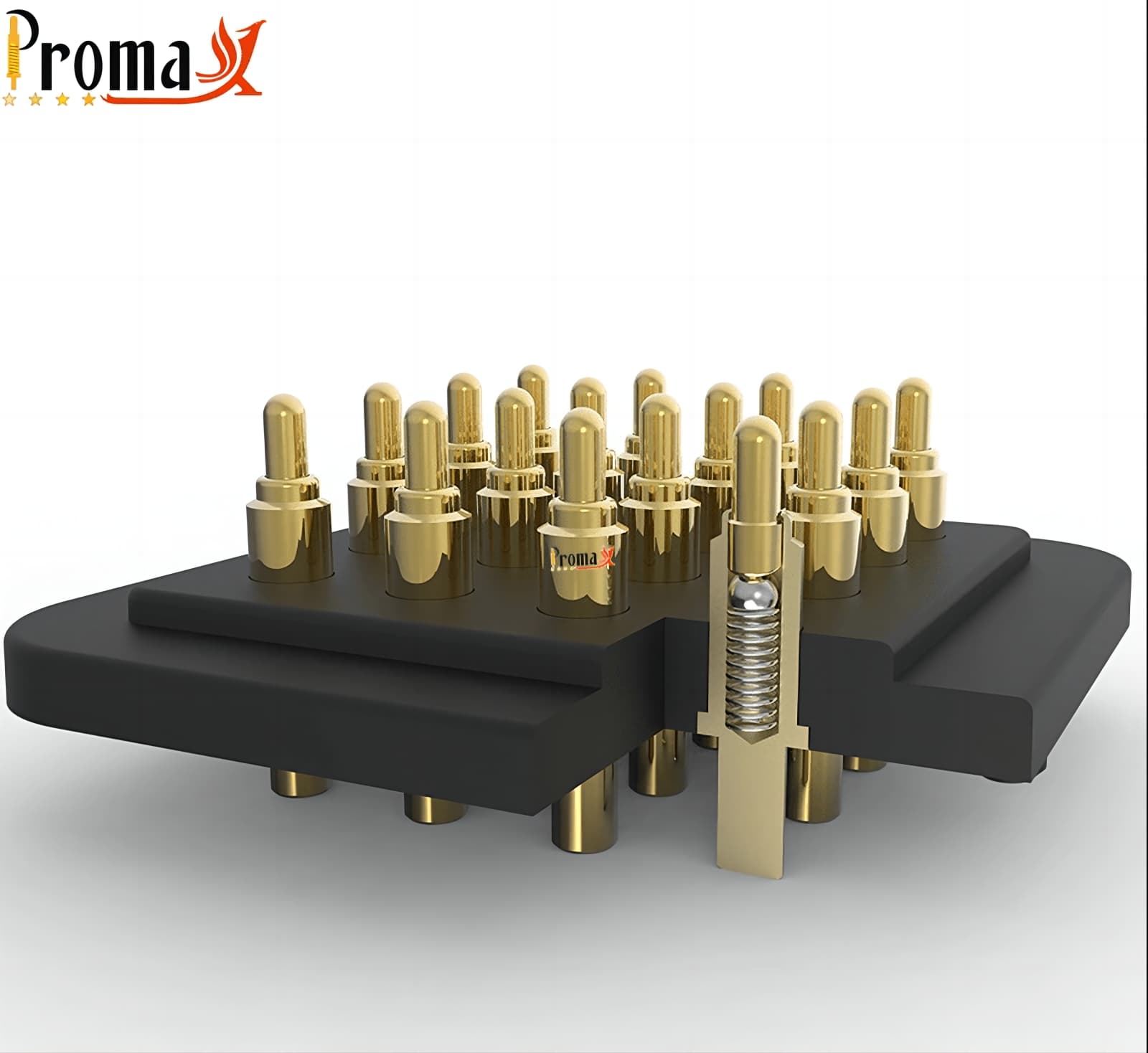
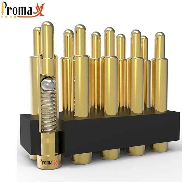
A spring-loaded connector is an electrical contact that uses a compressed internal spring to hold contact force between two mating surfaces. The spring keeps pushing even as the surfaces shift slightly. That constant force is what lets the connection survive thousands of cycles instead of failing after the first bit of vibration or misalignment.
That’s the key difference from a rigid, fixed contact: a spring-loaded connector compensates for movement instead of fighting it. You’ll also see this part called a spring-loaded pin connector, or simply a pogo pin, depending on the industry. Spring clips and terminal blocks share the “spring connector” name, but they solve a different problem and sit outside this guide.
How do Spring-Loaded Connectors Work?
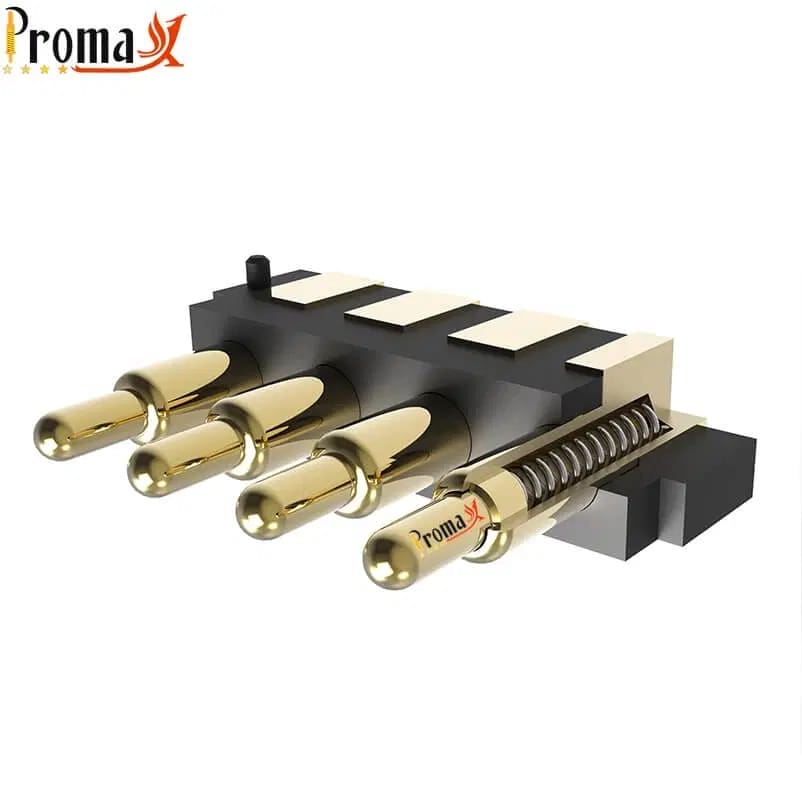
Every spring-loaded connector runs on the same basic mechanism: a plunger, a barrel, and a spring working as one unit. The details of that mechanism are where the real engineering trade-offs live.
Spring force and contact engagement
Spring force is the push that keeps the plunger seated against the mating surface. Too little force, and the connection drops out under vibration or shock. Too much, and you wear through the plating faster than the design life calls for.
A well-specified spring lands in the middle: firm enough to hold contact, gentle enough to protect the plating over the connector’s working life. Spring force is customizable to the application. Standard configurations commonly fall in the 50–200 gf range, depending on spring material, wire diameter, and coil geometry.
Contact resistance and the wiping action
Here’s the detail most guides skip: contact resistance stays low over time because of how the plunger moves. It’s not just the plating. As the pin compresses, the plunger rotates slightly against the mating surface.
That small rotation scrapes away oxide film and surface contaminants with every cycle. That’s why a well-designed pogo pin keeps a clean, low-resistance contact long after a static pad would have corroded. IEEE research on fretting corrosion models this exact mechanism: wipe versus corrosion buildup, cycle by cycle.
Plating still matters here. It sets the baseline resistance and how well the surface resists oxide buildup. But the wiping action keeps the contact clean cycle after cycle.
Plating and long-term wear
Gold and Nickel plating solve different problems, and the trade-offs are cycle life against cost. Gold plating resists oxidation and holds a lower, more stable contact resistance over the connector’s life. That’s why it shows up on connectors rated for high mating cycles or low-signal applications.
Nickel plating costs less and works fine for lower-cycle, less resistance-sensitive applications, but it wears and oxidizes faster under repeated contact. Neither option is universally better. The right plating depends on how many cycles the design needs, how sensitive the signal is to resistance drift, and what the budget allows.
Precision as a system outcome
It’s tempting to credit precision to one part, usually the spring. That’s not accurate. Precision in a spring-loaded connector comes from the entire stack working together: alignment tolerance, spring travel, plating consistency, and careful assembly.
Loosen any of those, and the others can’t fully compensate. A perfectly specified spring in a poorly aligned housing still delivers an inconsistent connection. Precise plating on a spring with the wrong travel range still wears unevenly. When you’re evaluating a supplier’s precision claims, ask about the system, not just the component.
The Complete Pogo Pin Family: Types of Spring-Loaded Connectors
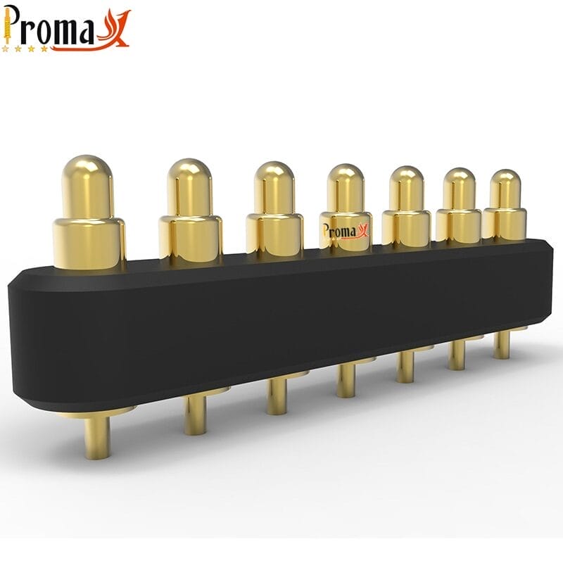
Seven families cover nearly every application for spring-loaded pogo pins. That range spans a Surface Mount Technology (SMT) pin reflow-soldered onto a wearable. It also spans a Printed Circuit Board (PCB) test probe cycling thousands of times a day. The table below maps them at a glance, and the breakdown that follows explains when each type earns its place in a design.
| Type | Mounting | Current handling* | Cycle life* | Best-fit application | Key trade-off |
|---|---|---|---|---|---|
| SMT / SMD | Solder pads, no drilling | Light to moderate | High-cycle rated | Consumer electronics, wearables, TWS earbuds | Smallest footprint; least mechanical retention |
| Through-hole | Drilled and soldered from the underside | Moderate to high | High-cycle rated | Test fixtures, prototyping, high-stress mounts | Strongest retention; needs the most drilled board space |
| High-current | Solder or press-fit larger barrel | Highest in the family | Plating-dependent | EV power delivery, battery management systems | Needs the most board real estate of any type |
| Double-ended | Press-fit or floating | Light to moderate | High-cycle rated | Stacked PCB assemblies, modular systems | Compensates both mating surfaces; adds stack height |
| Right-angle / bent-leg | Edge-mount | Light to moderate | High-cycle rated | Thin or constrained enclosures | Reduced stroke compared with a vertical pin |
| Magnetic connector | Magnet-and-spring assembly | Light to moderate per pin | High-cycle rated | Wearables, docking stations, quick-connect | Added cost; magnetic field needs shielding consideration |
| Test probe | Fixture-mounted | Application-dependent | Very high-cycle, built for fixture duty | PCB test and QA, bed-of-nails fixtures | Built for a fixture’s duty cycle, not product-level use |
Table 1. Deliberately qualitative. Exact current and cycle-life figures live once, in the Key Specs table below, so no number gets restated across the article.
SMT pogo pins
SMT pogo pins, also called Surface Mount Device (SMD) pins, solder straight onto the board. A pick-and-place machine then handles them the same way it handles every other surface-mount part. That makes them the default choice for consumer electronics and wearables, where board space is tight and assembly needs to stay automated.
The trade-off is mechanical retention. Without through-hole barrels anchoring them, SMT pins depend more on solder joint integrity and less on a physical lock into the board. Our PCB footprint guide for pogo pins covers the pad, pitch, and keepout rules that make those solder joints reliable.
Choose SMT when your current needs are light to moderate and your priority is footprint over ruggedness. Contact resistance on a well-plated SMT pin holds up well over the connector’s life, which matters for lower-power signal and charging applications.
Through-hole pogo pins
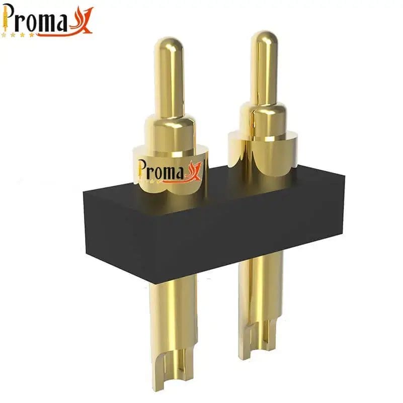
Through-hole pogo pins solder from the underside of the board, with the barrel anchored through a drilled hole. That’s different from just resting on a solder pad. It gives them the strongest mechanical retention in the family.
That’s why they show up in test fixtures, prototyping rigs, and mounts that take repeated physical stress. The trade-off is board space: drilling and through-hole soldering need more real estate than a surface-mount footprint.
This type makes sense when retention matters more than density. If your design gets handled, re-mated, or stressed mechanically on a regular basis, through-hole is usually the safer starting point.
High-current pogo pins
High-current pogo pins trade footprint for capacity. A larger barrel diameter carries meaningfully more current than a standard pin. That’s exactly what EV power delivery and battery management systems need from a spring-loaded contact.
The larger barrel does cost you board space, and current capacity always depends on pin diameter and plating working together, not the type alone. If your application pushes past what a standard pin can safely carry, this is the family to specify. For the full breakdown of current derating, plating choices, and design considerations, see our high-current pogo pin guide.
Double-ended pogo pins
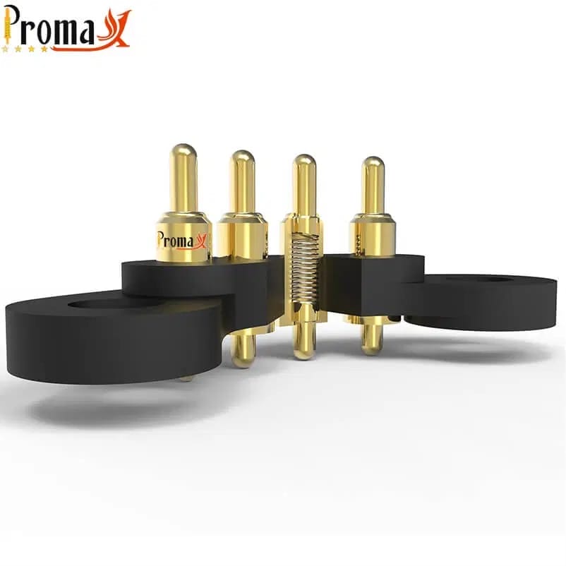
Double-ended pogo pins put a spring at both mating surfaces instead of just one, so they compensate for misalignment on either side of the connection. That makes them a natural fit for stacked PCB assemblies and modular systems, where two boards need to float independently and still land a reliable contact.
The trade-off is stack height: compensating both surfaces takes more vertical space than a single-ended pin. Reach for a double-ended design when your assembly has tolerance stack-up on both sides of the connection, not just one.
Right-angle and bent-leg pogo pins
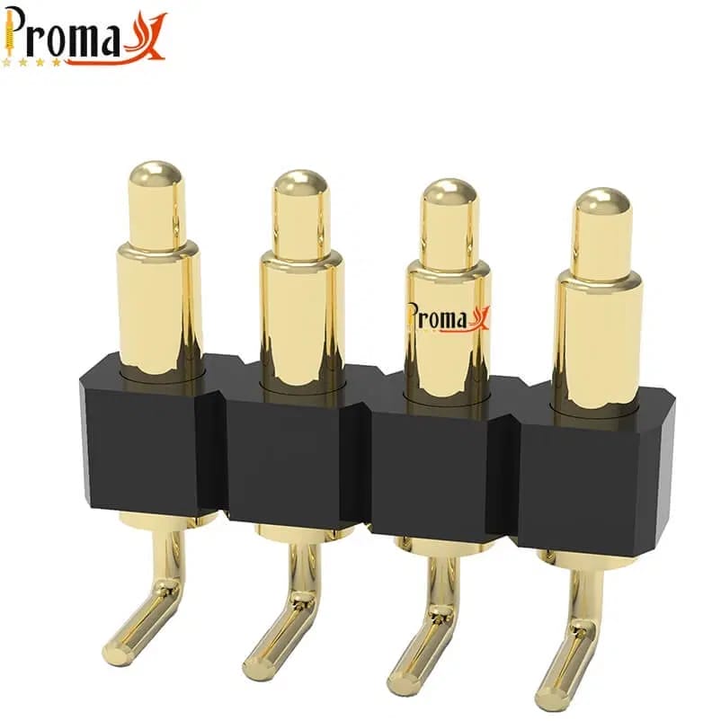
Right-angle and bent-leg pogo pins mount at the board’s edge instead of standing vertically. That frees up height in enclosures where a standard pin simply won’t fit. Thin or space-constrained designs, like slim wearables or edge-mounted connectors, are where this type earns its keep.
The trade-off is stroke: bending the leg reduces the usable travel compared with a vertical pin, so it compensates for less misalignment. Specify a right-angle pin when enclosure height is your binding constraint and the mating tolerance is otherwise tight.
Magnetic connectors
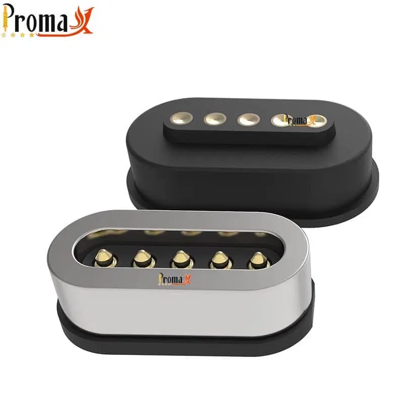
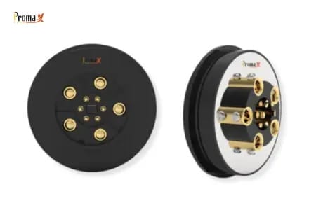
Magnetic connectors pair a spring-loaded contact with a magnet that pulls the two halves into alignment on their own. The user doesn’t have to line up pins by hand. That’s what makes them the default for wearables, docking stations, and any quick-connect application where blind mating matters.
Configurations range from a single contact up to multi-pin arrays, spanning 1–22 pins depending on the application, including USB-C variants. The added magnet brings extra cost and needs some thought around electromagnetic interference (EMI). A magnetic field sitting next to sensitive electronics isn’t always free.
Reach for a magnetic connector when the user experience of connecting matters as much as the electrical spec, not just when tolerance compensation does. For the full range and configuration options, see our magnetic connector guide.
Test probes
Test probes look like other pogo pin types, but they’re built for a different job. That job is fixture duty inside PCB test and quality assurance, not product-level connections. A bed-of-nails fixture might cycle a single probe more often in a week than a product-level pin sees in its entire service life.
Test probes get engineered around that duty cycle specifically. If you’re sourcing contacts for an in-circuit test fixture rather than a finished product, specify from this category. The selection criteria differ from a product connector.
Spring-Loaded Connectors vs. Other Connector Types
“Spring connector” sometimes means something other than a pogo pin, as mentioned above. Here’s where that distinction pays off. The table below places spring-loaded pogo pin connectors next to other connector families that share some of the same territory. You’ll see where each one actually wins.
| Connector family | Mating style | Reusability | Tolerance compensation | Typical use | When a pogo pin wins |
|---|---|---|---|---|---|
| Spring-loaded (pogo pin) | Compression contact | High; built for repeated mate/unmate | Absorbs misalignment and board flatness variation via spring travel | Docking, charging, testing, and board-to-board where cycling matters | Repeated connections, blind mating, tolerance stack-up |
| Board-to-board header | Pin-in-socket engagement | Moderate | Rigid; relies on tight positional tolerance | Fixed board stacking | Rarely; the pogo pin wins where cycling or misalignment is a factor |
| FPC / FFC connector | Ribbon clamped into a housing | Low; not built for frequent re-mating | Minimal | Flex-to-board signal runs | When the interface must re-mate often or survive shock |
| Terminal block | Screw or clamp onto a wire | Low | None | Field wiring, power distribution | When a repeatable, tool-free board-level contact is needed |
| Spring finger/clip contact | Cantilever wipe | Moderate | Some, via beam deflection | Grounding, shielding, low-cycle contact | When defined contact force and long cycle life are required |
This comparison is directional and qualitative. It maps connector families to typical roles, not exact specifications. The right choice depends on the application. Confirm your specific requirements with an engineer before finalizing a design.
Key Specs to Specify
Seven parameters determine whether a spring-loaded connector actually works in your design, and none of them stand alone. Each one shifts with a specific factor: part design, material, size, or what your supplier can actually build. The table below pairs every spec with the driver behind it, so a number reads as a starting point instead of a blanket promise.
These parameters aren’t arbitrary either. Most trace back to IEC 61076, the generic specification for connectors used in electronic equipment. Test methods historically defined in MIL-STD-1344 shaped this too, now largely carried forward by EIA-364.
| Parameter | Why it matters to the buyer | What drives the achievable number | Representative capability |
|---|---|---|---|
| Current rating | Determines whether the pin carries the load without overheating | Pin diameter, plating, contact geometry | Up to 40A in high-current configurations. The exact ceiling depends on pin diameter and plating. |
| Voltage rating | Sets safe operating headroom | Insulation material, creepage and clearance, housing design | Up to 120V, depending on housing and insulation design. |
| Contact resistance | Lower resistance means less signal loss and less heat at the joint | Plating type and thickness, contact geometry, spring force | Below 30 mΩ in standard configurations; tighter with heavier Gold plating. |
| Mating cycle life | Determines how long the connector holds up under repeated use | Plating, spring material, contact force, operating environment | 100,000+ cycles achievable with the right plating and spring pairing. |
| Spring force | Balances reliable contact against premature wear | Spring material, wire diameter, coil geometry | Fully customizable to the application; see “Spring force and contact engagement” above for typical ranges. |
| Pitch and pin count | Controls how densely contacts can be packed | Barrel diameter, housing tolerance, assembly process | Pin arrays scale from a single contact to multi-pin configurations for magnetic connectors; SMT pitch scales with barrel size. |
| Operating temperature | Confirms the part survives the product’s real thermal range | Housing material, plating, spring material | Range depends on material and plating selection. Confirm this against your application spec. |
Need pogo pins fast? Talk to an engineer
Get a custom quote, spec matching, and manufacturing guidance—without slowing down your project.
- ISO 9001 / 14001 / 45001 + IECQ QC080000
- 15+ years of expertise
- Free samples
- Mass production in 15–20 days
How to Select the Right Spring-Loaded Connector
Picking a spring-loaded connector isn’t one decision. It’s five, in a specific order, and getting the sequence right saves you from redesigning a footprint after you’ve already picked a part number. Walk through these five questions the way you’d walk a colleague through the reasoning out loud.
| Step | Question to ask | What it rules in / out |
|---|---|---|
| 1 | How much current and voltage does the circuit actually need? | Rules out standard SMT once load climbs past a few amps; points toward high-current types |
| 2 | How many mate and unmate cycles will this connector see over the product’s life? | Separates fixture-grade test probes from lighter consumer-duty pins |
| 3 | How much PCB real estate and stack height can you spare? | Filters mounting type: SMT vs. through-hole vs. right-angle vs. double-ended |
| 4 | Does the connection need blind mating, tool-free release, or fixed alignment? | Points toward magnetic connectors when blind or quick-connect matters |
| 5 | What’s the production volume, and how fast do you need samples and parts? | Shapes the custom-versus-standard conversation and the manufacturing timeline |
Work through the five in order, and you’ll land on a type, a mount, and a rough spec envelope before you ever look at a datasheet.
Why is Demand for Spring-Loaded Connectors Growing?
Device miniaturization keeps shrinking the space available for every connection, and spring-loaded connectors fit into gaps a traditional connector can’t. Wearables and true wireless stereo earbuds are a big part of that pressure. Each new generation needs a smaller charging or data contact than the one before it.
Electric vehicle battery management and autonomous sensor arrays add a different kind of demand. These connections carry serious current and still survive years of thermal cycling and vibration. Test automation is pushing volume too. Every board a factory tests in-circuit needs a probe that can survive its fixture’s duty cycle without drifting out of spec.
Medical device manufacturing rounds out the picture, where compact, sterilizable, high-reliability contacts are becoming standard rather than exceptional. That shift is pulling pogo pins into portable diagnostics and wearable monitors that used to rely on hardwired connections.
One market estimate, from research firm Dataintelo, puts the global pogo pin connector market at $1.69 billion in 2025. That figure is projected to grow toward $3.29 billion by 2034, a compound annual growth rate (CAGR) of 7.8%. That growth is driven largely by the same forces above: miniaturization, automotive electrification, and 5G test infrastructure.
That’s useful context for understanding the category. What matters for your design is which of these pressures applies to your application and which family in the table above answers it.
Common Applications

Consumer electronics remains the biggest volume driver, where board space is tightest and SMT and magnetic types dominate. Wearables and true wireless stereo earbuds push the miniaturization pressure even further, favoring the smallest, lightest configurations available.
Medical devices ask for something different: sterilizable housings and consistent contact resistance for sensitive sensor signals. Reliability has to hold up through repeated use in clinical settings.
Automotive and electric vehicle electronics lean on high-current types for battery management and power delivery. Vibration resistance and thermal cycling matter here as much as raw current capacity.
Test and quality assurance fixtures push cycle life harder than any product application. That’s exactly why test probes exist as their own category instead of borrowing a product-grade pin.
Industrial automation and aerospace round out the list. Environmental tolerance, often defined by an Ingress Protection (IP) rating, and long-term reliability outweigh cost as the deciding factor here.
How Promax Pogo Pin Delivers Custom Solutions
22+ patents and 8,000+ custom pogo pin designs sit behind Promax Pogo Pin’s approach to this whole pogo pin family. That work spans SMT and through-hole pins, magnetic connectors, and test probes. That depth means a design engineer gets more than a catalog part. It means an actual review of your spring force, plating, and tolerance requirements before anything ships.
Lead times follow the same discipline. Our engineers typically respond to a design request within 1–3 days. Samples ship within 2 weeks, and full production runs 3–4 weeks out. Send your board layout and spec sheet, and you’ll hear back with a real recommendation, not a generic quote.
Spring-Loaded Connector FAQs
What is the difference between a pogo pin and a spring-loaded connector?
A pogo pin is a spring-loaded connector. The terms describe the same three-part mechanism: plunger, barrel, and spring. “Spring-loaded connector” is the broader engineering term, while “pogo pin” is the common industry name, especially in consumer electronics and test equipment. The one exception is when “spring connector” refers to a mechanical clip or terminal block, which works differently and isn’t part of this family.
Do spring-loaded connectors stay reliable under vibration and shock?
Yes, when the spring force and housing are specified correctly for the application. The internal spring maintains constant contact pressure even as the boards shift slightly, which is exactly what a rigid contact can’t do under vibration. Reliability drops when the spring force is too light for the load or the housing doesn’t constrain lateral movement. Match the spring force and mounting to your vibration profile, and the connection holds.
Are spring-loaded connectors waterproof or IP-rated?
Standard pogo pins are not inherently sealed, but IP ratings are achievable with the right housing and gasket design. Sealing typically happens at the connector housing or device enclosure level, not the pin itself. If your application needs a specific IP rating, that requirement shapes the housing design from the start, not as an afterthought.
Can I get custom spring-loaded connectors in small quantities?
Yes, custom spring-loaded connectors are available in small quantities for prototyping and qualification testing. That typically happens through a free sample program before you commit to a production order. Minimum order quantities (MOQ) for full production runs vary by design complexity and configuration. Ask your supplier for their specific MOQ policy before finalizing a design.
What lead time should I expect for custom spring-loaded connectors?
Lead times depend on design complexity, customization, and order volume. Engineering feedback typically comes back fast, and sample and production timelines follow once your specs are locked in. For the specific design response, sample, and production timelines, see the custom-solutions section above.
Back to Top : Spring-Loaded Connector: The Complete Pogo Pin Family Guide
Need pogo pins fast? Talk to an engineer
Get a custom quote, spec matching, and manufacturing guidance—without slowing down your project.
- ISO 9001 / 14001 / 45001 + IECQ QC080000
- 15+ years of expertise
- Free samples
- Mass production in 15–20 days