Your Reliable Pogo Pin Manufacturer
A Pogo pin or spring loaded pin is a connector widely used in modern electronics. Dongguan Promax is a professional pogo pin manufacturer. Experts in the field of high precision, unique, intelligent pogo pins, confident in the design, quality, manufacturing technology, service, and delivery!
Ensure > 95% sample FPY and > 99% volume production FPY. (FPY: First Pass Yield, is the quality indicator)As the world’s leading pogo pin manufacturer, Dongguan Promax offers excellent ODM services and competitive prices.
Pogo Pin


Safe & On-Time Delivery
Leave your requirements and let Dongguan Promax handle the rest.

24/7 Online Support
Dongguan Promax is always here to support your business.

Competitive Price
Get better shipping rates to reduce your costs.
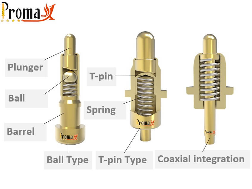
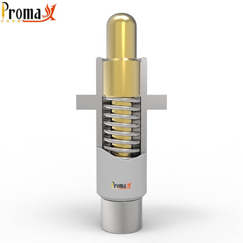
Pogo pin design
A Pogo pin consists of three main parts: a spring loaded plunger pin, a spring loaded locking pin, and a spring. Based on customer requirements, we can implement various designs such as Bias Tail, Back Drilling, Ball, T-pin, or Coaxial.
These specialized designs can reduce the electrical resistance of the Pogo pin, thereby accommodating high current demands from customers.
How about our product quality?
Our precision is second to none, thanks to our rigorous analysis of NC4891 sample size data. With a Cpk value of 0.98~1.12, we maintain a failure rate of just 0.5‰~0.9‰.In other words, only 5~9 wrong products emerge from every ten thousand. It’s an impressive feat, and we’re not done yet.
We’re committed to mastering the complete quality control system, pushing towards our ultimate goal of Cpk1.33. With us, you can trust that your products will be nothing short of exceptional.


Gage R&R (ANOVA) for Press Fit
We leave nothing to chance regarding quality control. For our press fit, we analyzed 100 pressure data points using the GR&R method. To ensure thorough testing, we had three technicians test the reproducibility and repeatability of the press fit across 10 different products. Our commitment to precision is unwavering, and our quality control measures are among the most rigorous in the industry. When you choose us, you choose excellence.


Pogo Pin Process
Our production process for Pogo pins includes six steps: turning, grinding, plating, assembly, inspection, and packaging.
First, brass is machined into a specific shape using a lathe, followed by tolerance adjustments with a grinding machine.
Next, the parts are sent to the plating facility for electroplating.
After plating, the components are sent to the assembly workshop. They then undergo inspection to ensure proper functionality.
Finally, the Pogo pins are packaged.

Our Customer Said
Dongguan Promax has assisted us with numerous on-site issues.
Their experienced engineers quickly resolved the high-temperature problem caused by excessive current in pogo pins.
I highly recommend them as a connector solution provider.
Paul Jelloy
Customer from UK
Package of pogo pin
We typically use reel packaging. First, the Pogo pins are placed on a custom-sized carrier tape, then rolled onto a reel using a tray. This method effectively prevents collision damage and reduces overall packaging space.
We have multiple automatic packaging machines, which are five times more efficient than manual methods, ensuring high production efficiency.
FAQ
What is pogo pin?

Spring loaded pin is an electrical connector structure used in modern electronic applications. They are more durable than other electrical connectors.
The name spring loaded pogo pin comes from the pin’s resemblance to a pogo stick – the integrated helical spring in the pin applies a constant normal force against the back of the mating receptacle or contact plate, counteracting any unwanted movement which might otherwise cause an intermittent connection.

What is Pogo Pins' Working Status?

- Free Height: is no load height, full extension height of spring
- Working Height: is the ideal load height for spring
- Maximum Load Height: is the maximum load height of the spring, usually, contacting the end of the barrel

Pogo Pins' Life Cycles

- At Dongguan Proma, the Spring loaded pin life cycle is in the range of 10,000 to 100,000 times
- Mechanical life cycle: maximum working times to ensure spring force in spec
- Electrical life cycle: maximum working times to ensure contact resistance in spec

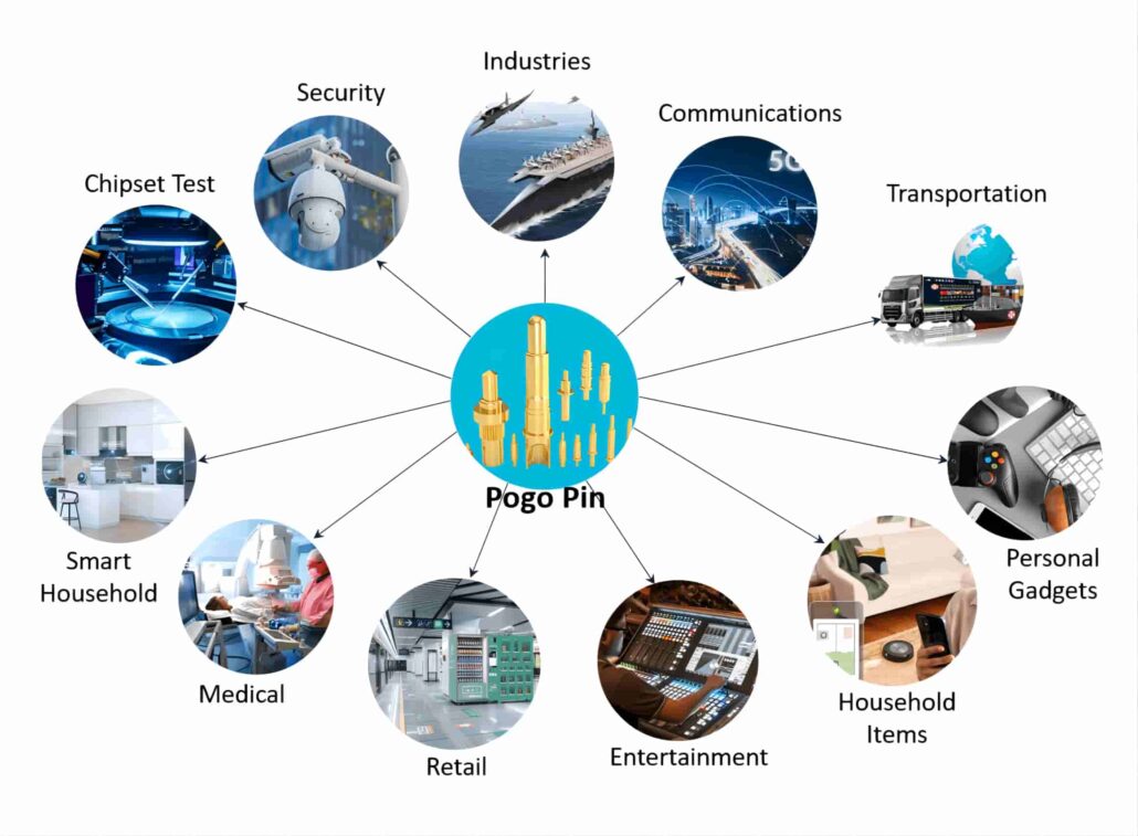
Pogo Pins' Applications

Dongguan Promax focuses on consumer electronics, new energy, chip testing, communications, smart home, medical, entertainment, security, retail, personal and industrial connector fields, and ODM services;
Always customer-centered, with the best technology, the highest quality, the best cost, the best service, the shortest delivery time, for Huawei, Millet, Amphenol, and other international and domestic well-known customers, to provide performance, life, reliability, security, economic and excellent products, and services!
With a perfect after-sales guarantee system, the service is more efficient, but also constantly expanding domestic and foreign high-quality customer groups!