ISO 9001, ISO 14001, ISO 45001, and IECQ QC080000
 Manufacturing Since 2014
 FREE samples provided to ensure product satisfaction
 Rapid Turnaround: Mass Production Complete in 15 - 20 Days

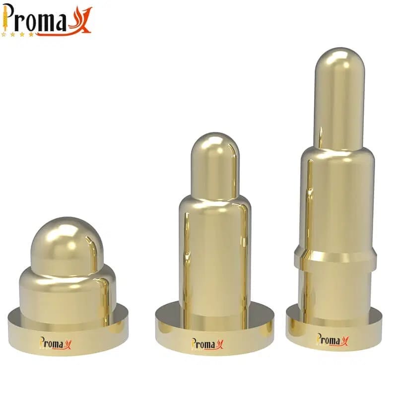
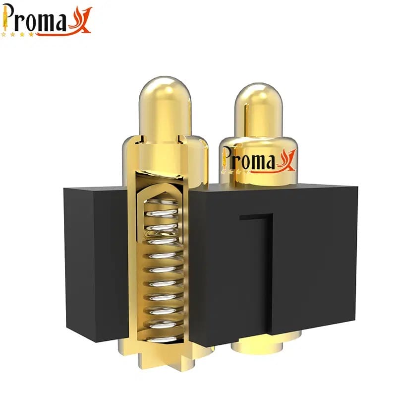
A pogo pin is a spring-loaded electrical contact built from three parts: a plunger, a barrel, and an internal spring. When you press it against a pad, it holds contact even when the two surfaces shift slightly.
That built-in give is the point of a spring-loaded connector. These contacts absorb tolerance stack-up, vibration, and thermal movement without dropping the connection. You’ll find them in consumer electronics, medical devices, automotive systems, and Printed Circuit Board (PCB) test fixtures.
This guide covers how pogo pins work, the main types, the specs that matter, plating options, where they’re used, and how to choose the right pin for your design.
Why are they Called Pogo Pins?
The name comes from the pogo stick. The internal spring gives the pin a press-compress-rebound motion, just like the toy. A popular story credits two designers, Pohlig and Gottschall, taking the first two letters of each surname to make “po-go,” though that origin isn’t well documented.
“Pogo” is also a registered trademark of Everett Charles Technologies, even though most of the industry now uses “pogo pin” generically. You’ll also hear spring-loaded connector, spring-loaded contact, spring probe, and spring-loaded pin. Each term leans on a different part of the same idea.
How does a Pogo Pin Work?
A pogo pin is a simple machine with one job: hold firm, repeatable contact between two surfaces that don’t always line up perfectly.
The three-component structure: plunger, barrel, and spring
The plunger is the moving tip that touches the mating surface, usually machined from Brass or Beryllium Copper and finished with a plating layer. The barrel is the outer housing that holds everything together and forms the interface to the board. Inside sits a helical spring that pushes the plunger outward with steady force.
When the spring force is right, the pin holds contact through vibration and thermal movement. Too little force, and the pin chatters or drops contact. Some designs add a small ceramic or metal ball between the spring and plunger for smoother travel and a more stable current path.
Why spring-loaded contact outperforms fixed connectors
A fixed pin has no give. It needs tight alignment, and it wears at the contact point every time it mates. A pogo pin absorbs the slack: the spring takes up misalignment and the small dimensional shifts that come with heat.
That tolerance makes blind mating practical. For a product team, the payoff is fewer field failures and lower warranty costs down the line.
What are the Main Types of Pogo Pins?
Pogo pins come in a handful of body styles. The right one depends on how much current you need to move and how much space you have. The table below lines them up side by side.
| Type | Mounting method | Current range | Cycle life | Best for |
|---|---|---|---|---|
| SMT | Reflow soldered to PCB pad | Up to 5A | 100,000+ | Consumer electronics, wearables, compact designs |
| Through-hole | Inserted through PCB, wave or hand solder | Up to 10A | 100,000+ | Higher-current designs, test fixtures, industrial |
| High-current | Through-hole or custom mount | Up to 40A | 100,000+ | EV charging, power delivery, battery connections |
| Double-ended | Press-fit or housed in connector | Varies by spec | 100,000+ | Board-to-board docking stations |
| Right-angle | SMT or through-hole, 90° orientation | Up to 5A | 100,000+ | Side-entry, space-constrained PCB layouts |
| Solder cup | Wire soldered directly to cup tail | Varies by spec | 100,000+ | Cable-end terminations, wire-bundle leads |
Current ranges and cycle life are representative. Actual values depend on pin diameter, plating specification, and operating conditions. Confirm exact values with our engineers before finalizing a design.
SMT pogo pins
Surface-mount technology (SMT) pins reflow-solder straight onto a PCB pad, the same way a chip does. They sit low and take up little room, which is why compact, height-sensitive products choose them. The trade-off is current headroom, and they’re fiddly to rework once they’re down. Choose SMT when board space and profile height drive the design, such as wearables and earbuds.
Through-hole pogo pins
Through-hole pins drop through a drilled hole and solder on the far side, which gives them a stronger mechanical grip than a surface pad. That anchoring helps in higher-current and higher-vibration jobs where you don’t want a contact shaking loose. You pay for it in board real estate. Reach for through-hole in industrial gear, test fixtures, and anything that takes a beating.
High-current pogo pins
When a pin has to move more power, it needs a larger barrel and plunger. The bigger contact area carries more current. Custom high-current designs can carry up to 40A depending on diameter, plating, and how hard the contact runs. The cost is size and unit price. Common applications include electric vehicle (EV) charging contacts, battery connections, and power delivery.
Double-ended pogo pins
A double-ended pin is spring-loaded on both tips instead of one. That lets it absorb tolerance on both mating surfaces at once. This helps when neither side sits at a guaranteed height. You’ll find them in board-to-board stacks, docking connectors, and modular designs where two assemblies meet and both can drift.
Right-angle and bending-type pogo pins
Right-angle and bending-type pins turn the contact 90 degrees from the board, so the connection comes in from the side rather than straight down. That side-entry geometry suits docks, charging cradles, and tight layouts where a vertical pin won’t fit.
Solder cup pogo pins
A solder cup pin skips the board entirely: the tail forms a small cup that takes a wire directly. You terminate a cable straight onto the pin. That makes them a fit for cable assemblies, handheld probes, and wire-ended contacts where there’s no PCB to mount to.
Magnetic Connectors: A Related Product Category
Add a couple of magnets to a pogo pin array, and the connector finds its own alignment. The magnets handle positioning and hold, while the pins handle all the electrical contact. At Promax Pogo Pin, we build magnetic connectors from 1 to 22 pins, including USB-C magnetic cable versions. We tune the magnet strength and pin layout to each product. It’s the same spring-loaded contact, dressed for blind, one-handed mating.
Test Probes: The PCB Testing Variant
Test probes are close cousins to product pogo pins, built for a different job. Instead of living inside a finished device, they sit in a fixture and press against a board’s test points to check it during manufacturing. They’re tuned for very high cycle counts. Their specialized tip shapes bite through solder mask or oxide to reach clean metal. We manufacture test probes alongside our pogo pins, on the same machining lines and under the same ISO-certified quality system. They’re related, but don’t treat them as interchangeable.
Need pogo pins fast? Talk to an engineer
Get a custom quote, spec matching, and manufacturing guidance without slowing down your project.
- ISO 9001 / 14001 / 45001+ IECQ QC080000
- 15+ years of expertise
- Free samples
- Mass production in 15–20 days
What Specs Matter When Choosing a Pogo Pin?

A pogo pin is only right for your design if its numbers line up with your application. Six or seven specs do most of the deciding, and they trade against each other—push one and another gives.
| Specification | Typical range | Promax max/customizable | Design implication |
|---|---|---|---|
| Current rating | 1–5A (SMT standard) | Up to 40A (high-current) | Underrated pins overheat and degrade contact integrity |
| Voltage rating | Up to 50V (standard) | Up to 120V | Insulation requirements increase with voltage |
| Contact resistance | 20–50 mΩ (standard) | Below 30 mΩ with Gold plating | Higher resistance means more signal loss and heat |
| Spring force | 50–200 gf | Fully customizable | Balances reliable contact against plating wear rate |
| Mating cycle life | 100,000+ cycles | 100,000+ (extended with Gold plating) | It must exceed product lifespan or it becomes the bottleneck |
| Plating | Nickel (standard) | Gold, Nickel, Palladium | Affects contact resistance, durability, and unit cost |
| Operating temp. | Per application | Confirm with our engineers | Temperature extremes affect spring constant and plating |
All values are representative typical ranges. Confirm application-specific data with our engineers before committing a design.
The overview table is a starting point, not a datasheet. Real values depend on the pin’s size, materials, plating, and build. Standards like IEC 60512 define how contact resistance and cycle life are measured, which is worth knowing when you compare one supplier’s figures against another’s.
Current and voltage rating
The current rating tells you how much the pin can carry before it heats up and degrades the contact. It depends on pin diameter, plating, and contact area more than on any single label. Surface-mount pins handle up to 5A, and high-current designs reach 40A. Voltage rating sits alongside it: standard pins handle up to 50V, and custom builds go to 120V. Insulation requirements rise as voltage climbs.
Contact resistance
Contact resistance is the small resistance right where the plunger meets the surface, measured in milliohms – typically 20–50 mΩ for standard pins. Lower is better: every milliohm turns a little power into heat and shaves signal quality. Plating choice moves this more than almost anything else. Specify the resistance you need at the end of life, not just the day it ships, because it drifts upward as the contact wears.
Mating cycle life
Cycle life is how many connect-disconnect rounds the pin survives before it falls out of spec. Standard pins are rated for 100,000+ cycles. A charging contact that mates twice a day lives a different life from a probe hammered all shift. Plating thickness, spring quality, compression ratio, and operating environment all set the real number. If the pin wears out before the product does, the connector quietly becomes the weakest link.
Spring force
Spring force is how firmly the plunger pushes back, typically 50–200 gf and fully customizable. Too light and the pin loses contact under shock. Too heavy, and it grinds the plating off both the tip and the pad. There’s a practical detail here: design for the working stroke, not the full travel. Run a spring much past about 70 percent of its total travel, and you compress it near solid height, which accelerates fatigue.
Plating material
Plating is the thin metal skin on the contact, and it sets resistance, corrosion protection, and life. Gold gives the lowest resistance and best wear life at the highest cost. Nickel is the workhorse baseline. Palladium and its alloys resist corrosion well for automotive and telecommunications.
Pogo Pin Plating Options Compared
Plating is where a lot of reliability quietly lives, and it’s the spec engineers most often underestimate. The material you pick changes contact resistance, how many cycles the pin survives, and how it stands up to humidity or salt. The table compares the common choices.
| Plating | Contact resistance | Cycle life | Corrosion resistance | Recommended applications |
|---|---|---|---|---|
| Gold | Lowest (below 20 mΩ) | Highest | Excellent | Medical, aerospace, high-cycle, and low-voltage signal contacts |
| Nickel | Moderate (30–50 mΩ) | Good baseline | Good | Consumer electronics, cost-sensitive, moderate-cycle designs |
| Palladium / PdNi | Low to moderate | High | Very good | Automotive, telecommunications, corrosion-resistant environments |
Values are typical ranges. We also offer custom plating options—contact our engineers for application-specific recommendations.
Where are Pogo Pins Used?
Pogo pins turn up anywhere a product needs a connection that’s made and broken a lot or that has to survive being dropped, charged, and handled for years. A few industries lean on them hard.
Consumer electronics and wearables
Earbuds, smartwatches, fitness bands, and phones use pogo pins for charging and data contacts, usually the low-profile surface-mount or magnetic styles. The push toward smaller, water-resistant devices keeps demand high for tiny pins that still seat reliably inside a sealed housing.
Medical devices
Patient monitors, hearing aids, and diagnostic tools use pogo pins where a connection has to stay clean and dependable through repeated use and sterilization. Gold plating tends to win here. Medical supply chains also care about quality documentation, so certifications like ISO 13485 enter the conversation early.
Automotive, EV, and aerospace
Cars and EVs put pogo pins in battery management, charging contacts, and cabin electronics. High-current variants carry the load, and vibration resistance is non-negotiable. Automotive is driving a lot of connector demand right now, especially EVs, per Grand View Research. Aerospace adds environmental extremes and MIL-STD testing on top.
PCB testing and industrial electronics
Bed-of-nails fixtures use dense arrays of spring-loaded probes to touch every test point on a board at once, rated for millions of cycles. More broadly, pogo pins handle docking stations, modular equipment, and quick-connect points on automated lines.
How to Choose the Right Pogo Pin for Your Design
Picking a pin gets easier if you go in order. Each step narrows the field, so by the end you’re choosing between a few real options instead of an entire catalog.
- Start with the electrical demands. Pin down current, voltage, and the contact resistance you can tolerate.
- Match the mount to your board. Surface-mount for compact builds, through-hole when you need mechanical hold, and solder cup when there’s no board at all.
- Set spring force for the environment, not the bench. A vibrating engine bay needs more force than a wearable on someone’s wrist.
- Choose plating that meets your reliability and cost targets. Gold for high-cycle, corrosion-sensitive, or medical work; Nickel when budget and cycle count both stay modest.
- Check cycle life against how long the product has to live. Match rated life to the real usage profile, not the optimistic figure.
- Confirm the environment. Temperature swing, ingress protection, chemical exposure, and altitude.
- Get samples and test in your own application. Datasheet numbers are a starting line; your real conditions are the finish.
Custom Pogo Pin Manufacturing with Promax
Everything in this guide is something we make at Promax Pogo Pin. We’ve focused only on spring-loaded contacts since 2014 and hold 22 patents in pogo pin technology. We’ve delivered over 8,000 custom designs for customers that include Huawei, Xiaomi, and Amphenol. Because we run our own 15,000 m² factory, we control plating, machining, and quality from end to end.
Send us your board layout and target pogo pin specifications. Our engineers respond within 1–3 days, with free samples to qualify in your own application before you tool up. We tune size, plating, current up to 40A, voltage up to 120V, spring force, and environmental tolerance to the job, backed by ISO 9001, ISO 14001, ISO 45001, and IECQ QC080000-certified production.
Pogo Pin FAQs
Is a spring-loaded connector the same as a pogo pin?
Mostly, yes. “Spring-loaded connector,” “spring-loaded contact,” and “spring probe” are all common names for the same family of parts, and “pogo pin” is the most widely used. The label often hints at the use: “probe” usually points to test applications, while “connector” points to product-level contacts.
Are pogo pins waterproof?
On their own, no. The gap between the plunger and barrel can let moisture in. Waterproof connections come from a sealed housing with gaskets or O-rings around the pin assembly. Properly housed, a pogo pin connection can reach IPX7 or IPX8 ratings.
How small can pogo pins get?
Pogo pins scale down to fine diameters and tight pitches for high-density layouts, with the practical floor set by the target pad size and machining tolerance. Smaller pins carry less current, so miniaturization always trades against power handling. The right minimum depends on your board layout and contact requirements.
Do pogo pins carry high-speed data or just power?
They do both. The same contact that delivers power can carry data, and well-designed pins support high-speed signals when impedance and pin layout are controlled. For fast data lines, contact resistance stability and a clean, short signal path matter more than raw current rating.
What’s the minimum order for custom pogo pins?
It depends on the design and the supplier—custom tooling and plating set the floor. Because pogo pins are turned rather than molded, smaller runs are more workable than with molded connectors. We provide free samples first so you can qualify a design before committing to a production quantity.
Can I get pogo pins made to my exact specifications?
Yes, custom pogo pin manufacturers like Promax Pogo Pin tailor diameter, length, plating, current and voltage rating, spring force, and environmental tolerance to the application. Engineering feedback typically takes 1–3 days, with samples to follow.
Back to Top: What Is a Pogo Pin? The Complete Guide to Spring-Loaded Connectors
Need pogo pins fast? Talk to an engineer
Get a custom quote, spec matching, and manufacturing guidance without slowing down your project.
- ISO 9001 / 14001 / 45001+ IECQ QC080000
- 15+ years of expertise
- Free samples
- Mass production in 15–20 days