ISO 9001, ISO 14001, ISO 45001, and IECQ QC080000
 Over 15 Years of Expertise
 FREE samples provided to ensure product satisfaction
 Rapid Turnaround: Mass Production Complete in 15 - 20 Days

Specify the wrong pogo pin, and the problems surface later: contact failures, thermal issues, or a board redesign. Getting the pin type right but the specs wrong produces the same result. Pogo pin specifications define the electrical and mechanical limits that separate a connector that works from one that works reliably.
Six core parameters decide most of that outcome: current rating, contact resistance, pitch, plating, cycle life, and Printed Circuit Board (PCB) footprint. The sections below connect each number to the design a consequence behind it. If you need the fundamentals first, start with our guide to what a pogo pin is.
Pogo Pin Specifications at a Glance
Before going spec by spec, here’s the full picture in one table.
| Specification | What It Measures | Typical Range | Affected By |
|---|---|---|---|
| Current rating | Max continuous amperage within safe temperature rise | 1–40A | Pin diameter, barrel thickness, plating, spring design, contact area |
| Contact resistance | Resistance at plunger–barrel and plunger–mating-surface interfaces | 20–50 mΩ standard; <10 mΩ high-performance | Plating material and thickness, spring force, surface cleanliness, pin geometry |
| Pitch/center spacing | Center-to-center distance between adjacent pins | 0.4–5.08 mm | Pin diameter, current requirement, PCB manufacturing capability |
| Plating type and thickness | Surface material and coating depth on contact surfaces | Gold 0.5–3 µm; Nickel; Palladium | Cycle life target, corrosion environment, cost budget |
| Cycle life | Mate/unmate cycles maintaining specified resistance and force | 10,000–1,000,000 | Plating thickness, spring force, operating environment, contamination |
| Spring force | Force exerted by an internal spring at a given compression point | 10–260 gf | Application type, mating surface hardness, cycle life target |
| Working stroke | Recommended compression range at 60–80% of total travel | Varies by pin length | Board-to-board gap, tolerance stack, mechanical reliability |
| Operating temperature | Ambient temperature range for reliable operation | −40°C to +85°C standard; to +125°C extended | Spring alloy, plating stability, housing material |
| PCB footprint | Board space occupied: pad size, drill hole, keep-out area | Correlates to pin diameter and mount type | Mount method, pitch, current requirement |
All values are representative. Verify against your specific manufacturer’s datasheet and engineering data.
How Specifications Vary by Pogo Pin Type
Not all pogo pins share the same specification ranges. The mounting method, form factor, and intended application determine which values are achievable. A Surface Mount Technology (SMT) pin for a smartwatch charging dock and a high-current pin for an EV battery dock occupy completely different ranges. The table below maps the major types to their typical specifications.
| Pogo Pin Type | Current Rating | Contact Resistance | Typical Pitch | Cycle Life | Mount Method | Best For |
|---|---|---|---|---|---|---|
| SMT | Up to ~5A | 20–50 mΩ | 1.0–2.54 mm | 50K–500K | Surface mount | Consumer electronics, wearables |
| Through-hole | Up to ~8A | 20–40 mΩ | 2.0–2.54 mm | 100K–1M | Wave/hand solder | Test fixtures, industrial |
| High-current | 10–40A | 10–30 mΩ | 3.0–5.08 mm | 50K–500K | Through-hole / press-fit | EV charging, power delivery |
| Double-ended | 1–5A | 30–60 mΩ | 1.27–2.54 mm | 100K–500K | Housed in connector | Board-to-board connections |
| Right-angle | 1–3A | 30–50 mΩ | 2.0–2.54 mm | 50K–300K | SMT / through-hole | Side-entry, limited clearance |
| Solder cup | 2–8A | 20–40 mΩ | 2.54–5.08 mm | 50K–500K | Wire termination | Cable-lead applications |
| Magnetic | 1–5A | 30–50 mΩ | 2.0–3.0 mm | 50K–300K | Magnetic self-align | Self-aligning docking |
Values are typical ranges. Actual specs depend on manufacturer, material, and pin geometry. Verify against your manufacturer’s product data.
SMT pogo pins
SMT pogo pins deliver the smallest footprint of any type and suit pick-and-place assembly lines. They’re the default for compact consumer electronics, where board space is measured in fractions of a millimeter. Current capacity typically tops out around 5A in standard configurations. Contact resistance sits in the 20–50 mΩ range with Gold plating.
Through-hole pogo pins
Through-hole mounting gives you the strongest mechanical bond to the PCB. The trade-off is a larger footprint and drilled holes, which consume board space on both sides. These pins handle more current than SMT variants, up to roughly 8A standard and higher in custom designs. They’re common in test fixtures and industrial equipment, where vibration tolerance matters more than miniaturization.
High-current pogo pins
High-current pins cover the 10–40A range. They use larger diameters, thicker barrel walls, and specialized internal designs that maximize the contact area between plunger and barrel. More contact area means less resistance and less heat at high amperage. The cost is board space, since these pins demand a wider pitch.
Other types worth knowing
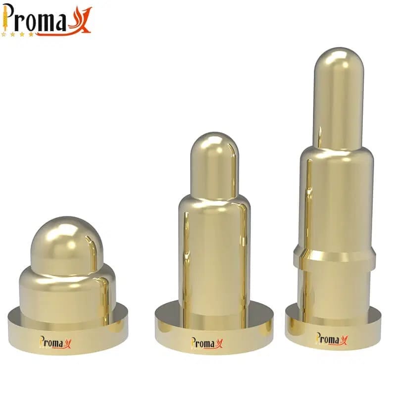
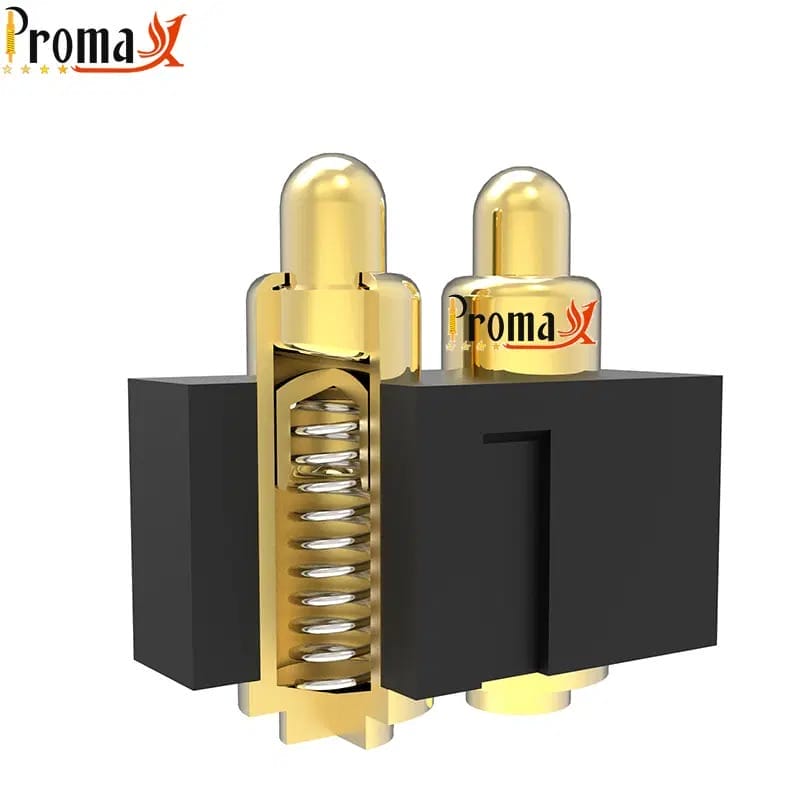
Double-ended pogo pins have spring-loaded contacts at both ends. That makes them the natural fit for board-to-board connections in stacked assemblies. Right-angle variants orient at 90 degrees for side-entry applications with tight vertical clearance. Solder cup pins terminate directly to wire leads. Magnetic pogo pins use embedded magnets for self-aligning, blind-mate docking, which you see in laptop charging docks and medical device cradles.
Current Rating: What it is and How to Specify it
Current rating is the maximum continuous amperage a pogo pin can carry without exceeding a safe temperature rise. It’s the first filter most engineers apply when choosing a pin. Get it wrong in one direction and the pin overheats, degrading the spring temper and accelerating contact resistance drift. Get it wrong in the other, and you waste board space on a pin larger than necessary.
What determines the rating? Pin diameter is the biggest lever. Barrel wall thickness, plating material, spring design, and the contact area at the plunger-barrel interface all play a role too. The relationship between diameter and current isn’t linear, either. A 2 mm pin with a ball-point internal contact can carry more current than a 2 mm pin with a straight spring, purely because of contact geometry.
Standard current ratings by pin diameter
The table below maps pin diameter to typical current capacity. These figures are guidance, not hard limits. Internal contact geometry, plating, and thermal environment all shift the real-world number.
| Pin Diameter | Typical Current Rating | Common Applications |
|---|---|---|
| 0.5 mm | Up to ~1A | Signal-only: I²C, SPI, UART, low-power sensors |
| 1.0 mm | 2–3A | Mixed signal and power in wearables, IoT devices |
| 1.5 mm | 3–5A | Moderate power delivery, charging contacts |
| 2.0 mm | 5–6A | Industrial connectors, test fixtures |
| 2.5 mm+ | 10–40A | EV charging, high-power docking, battery contacts |
All values are typical guidance. Verify against specific manufacturer datasheets.
What happens when you exceed the current rating?
Sustained overcurrent causes a temperature rise that degrades the spring’s temper over time. The spring loses force, and contact resistance climbs. In extreme cases, the plating can melt at the contact interface. It’s a slow slide that surfaces only after weeks or months in the field, which makes it hard to catch during prototyping.
A practical rule: derate by 20–30% for continuous operation in enclosed spaces with limited airflow. Datasheet current ratings assume open-air convection. Inside the sealed housing of a wearable or a medical device, the thermal environment is far less forgiving.
High-current pogo pins
The 10–40A range calls for specialized internal designs. Larger diameters and thicker barrel walls are part of the answer, but the contact geometry inside the pin matters just as much. Slant-bottom and bias-tail designs maximize the plunger-barrel contact area, which keeps resistance low at high amperage. The trade-off is more board space and wider pitch, so plan the PCB layout for the wider footprint from the start. For the full layout workflow, see our pogo pin design guide.
Contact Resistance
Contact resistance is the electrical resistance at the two interfaces where metal meets metal: plunger to barrel, and plunger to mating surface. It’s measured in milliohms. Every milliohm matters. In power applications, it means heat; in signal applications, it means voltage drop.
Standard gold-plated pogo pins typically sit in the 20–50 mΩ range. High-performance designs can achieve under 10 mΩ in specialized configurations. That figure depends heavily on plating thickness, spring force, and how clean the contact surfaces are.
What affects contact resistance?
Plating material is the biggest factor. Gold gives the lowest resistance; Nickel runs two to three times higher. Pin geometry and the precision of the plunger-barrel fit matter too. A tighter machining tolerance at that interface shortens the resistance path.
Higher spring force pushes the plunger more firmly against the mating surface. That breaks through surface oxides and lowers resistance. But more force also accelerates plating wear, which raises resistance over time. It’s a trade-off, and getting the specification right means understanding it.
One point worth knowing: contact resistance measured at the pin alone can differ from the pin-plus-mating-surface value by two to five times. When comparing vendor datasheets, confirm the measurement configuration. A 30 mΩ reading at the pin alone and a 30 mΩ reading across the full mated assembly describe very different performance.
Contact resistance drift over cycle life
Contact resistance isn’t a fixed number. It rises over the life of the pin as the plating wears through. Gold erodes down to the Nickel underplate across thousands of mating cycles. Once the Gold layer is breached, resistance climbs steeply. This is the knee in the lifecycle curve, and it’s why plating thickness and cycle life are linked specifications.
If your application needs stable resistance beyond 100,000 cycles, specify a minimum plating thickness. Ask your manufacturer for lifecycle test data that proves the resistance profile at your target cycle count.
Pitch and Center Spacing
Pitch is the center-to-center distance between adjacent pogo pins in a connector or array, measured in millimeters. Common values run from 0.4 mm for ultra-fine test probes up to 5.08 mm for high-current industrial connectors. The most widely used standard is 2.54 mm. That’s 0.100 inches, the same grid spacing on legacy through-hole PCB designs.
How pitch affects your design
Smaller pitch means more pins per unit of board area. That sounds positive, but finer pitch tightens PCB manufacturing tolerances and raises signal crosstalk risk between adjacent pins. Physical alignment during mating also gets harder. Below 1.27 mm, crosstalk becomes a real concern for high-speed data. Shielded or coaxial pogo pins exist for these cases, but they add cost and complexity.
Match pitch to the application. Test fixtures commonly use 2.54 mm. Consumer electronics charging docks sit in the 2.0–3.0 mm range. High-density board-to-board connections push down to 1.0–1.27 mm. Those need tighter PCB tolerances and more careful alignment to work reliably.
Pitch and current rating
Higher current requires a larger pin diameter. A larger diameter requires a wider pitch. This cascade means a 40A high-current pin cannot fit on a 1.27 mm grid; the pin is physically too large.
When specifying pogo pins for power delivery, work backward. Start from the current requirement, then the minimum diameter, then the minimum pitch, then the board-space budget. That sequence prevents a common mistake: designing a dense pinout, then finding no pin meets the current requirement at that spacing.
Plating Types and Thickness
Plating directly affects contact resistance, corrosion resistance, wear rate, and cost. It’s one of the most consequential specifications on a pogo pin datasheet and one of the most frequently underspecified. Engineers often default to Gold. A thinner Gold layer, a Palladium alternative, or even Nickel can be the better match for a given cycle life target and budget.
Gold plating
Gold leads in high-reliability applications for good reason. It offers the lowest contact resistance of any common plating material, excellent corrosion resistance, and the longest cycle life. Typical thickness ranges from 0.5 to 3 µm. Thinner Gold, around 0.76 µm, works for cost-sensitive applications with moderate cycle counts.
Coatings of 2–3 µm are the go-to for high-cycle or corrosive environments. Gold-on-gold contact, where both the pin and the mating surface are gold-plated, is the established approach for stable resistance over 100,000 or more cycles.
Nickel plating
Nickel costs less than Gold and offers good hardness and wear resistance. The trade-off is higher contact resistance, roughly two to three times what you’d see with Gold. Nickel also forms a thin oxide layer over time. That can further raise resistance in humid or corrosive environments. For lower cycle counts and cost-sensitive applications, it’s a practical choice.
Nickel serves a second role as an underplate beneath Gold. It provides adhesion to the base metal and acts as a diffusion barrier. That barrier stops the underlying copper or brass from migrating into the Gold layer.
Palladium and other options
Palladium and Palladium-Nickel alloys sit between Gold and Nickel in both cost and performance. They suit automotive and telecommunications connectors, where the cycle life requirement exceeds what Nickel can deliver, but the budget doesn’t justify full Gold.
Silver offers lower contact resistance than Gold but tarnishes readily in sulfur-containing environments, which limits it to sealed or inert atmospheres. Tin is the lowest-cost option. Its softness means it wears quickly, so it’s best for disposable or low-cycle applications where connector longevity isn’t a priority.
Plating comparison table
| Plating Material | Contact Resistance | Corrosion Resistance | Cycle Life Impact | Best For |
|---|---|---|---|---|
| Gold (Au) | Lowest (baseline) | Excellent | Highest—thickness extends life | High-reliability, medical, aerospace, >100K cycles |
| Nickel (Ni) | 2–3× higher than Gold | Good—forms oxide over time | Moderate-hard surface resists wear | Cost-sensitive, low cycle, Gold underplate |
| Palladium (Pd/PdNi) | Between Gold and Nickel | Very good | Good — excellent wear resistance | Automotive, telecom, volume-sensitive |
| Silver (Ag) | Lower than Gold | Poor—tarnishes in sulfur | Moderate — soft, wears under friction | Sealed/inert environments, specialized RF |
| Tin (Sn) | Higher than Nickel | Moderate — stable oxide | Low — soft, wears quickly | Lowest cost, disposable, low cycle |
Values are comparative. Actual performance depends on plating thickness, underplate, base material, and operating environment.
Need pogo pins fast? Talk to an engineer
Get a custom quote, spec matching, and manufacturing guidance—without slowing down your project.
- ISO 9001 / 14001 / 45001 + IECQ QC080000
- 15+ years of expertise
- Free samples
- Mass production in 15–20 days
Cycle Life – What do the Ratings Really Mean?

Cycle life is the number of mate and unmate cycles a pogo pin survives while holding contact resistance and spring force within limits. Rated ranges span from around 10,000 cycles for basic consumer applications to 1,000,000 cycles for high-performance test probes. Standard industrial and commercial pogo pins typically carry a 100,000-cycle rating.
Rated vs. real-world cycle life
Datasheet ratings come from controlled lab conditions: clean contact surfaces, stable temperature, and consistent mating force. Real-world cycle life is typically 50–70% of the rated value. Actual operating environments add contamination, temperature swings, and force inconsistencies that speed up wear.
A practical buffer: if your product’s warranty or service life needs 50,000 mating cycles, specify a pin rated for at least 100,000. That margin covers the environmental factors a datasheet can’t simulate.
What shortens cycle life?
Excessive spring force speeds up plating wear on both the plunger tip and the mating pad. Operating beyond the working stroke causes spring fatigue. Environmental exposure degrades both the plating and the spring alloy. Contamination at the contact interface, whether flux residue, dust, or finger oils, creates resistive barriers.
PCB Footprint and Mounting Dimensions
The PCB footprint is the physical space a pogo pin occupies on the board. That covers pad dimensions for SMT, drill hole diameter and annular ring for through-hole, and keep-out areas for spring compression clearance. The footprint ties directly to pin type. Choosing a type without checking its footprint against your available board space is a fast path to a redesign.
SMT vs. through-hole footprint comparison
SMT pogo pins have the smallest footprint. The pad size correlates to pin diameter, and no drill holes are required, so the footprint affects only one side of the board.
Through-hole pins need a plated through-hole with enough annular ring for a reliable solder joint. The bond is stronger, but the footprint consumes board space on both sides.
The drill holes also constrain routing on inner layers. For high-density designs, SMT is almost always the answer. For high-vibration environments where mechanical robustness beats density, through-hole earns its keep.
Working stroke and board-to-board spacing
Working stroke is the recommended compression range where the pin performs optimally. It directly sets the minimum gap between mating boards or surfaces. Specify the working stroke, not the maximum stroke, when setting board spacing.
Over-compressing the pin past its working range causes spring fatigue and shortens cycle life. Many engineers design to the maximum stroke by mistake because it’s the bigger number on the datasheet. The working stroke is the correct design parameter.
How does Spring Force Affect Reliability and Wear?
Spring force is the force that an internal spring exerts at a given compression point. It’s specified at initial contact and at the mid-compression working point in grams-force or newtons. Typical ranges run 10–60 gf for consumer product pins, 50–200 gf for standard industrial applications, and 100–260 gf for high-current configurations.
Spring force is not a higher-is-better parameter. More force improves contact reliability by breaking through surface oxide layers. That’s why test fixtures contacting re-flowed boards with flux residue need heavier springs.
But more force also accelerates plating wear on both the plunger tip and the mating pad, which shortens cycle life. For clean mating surfaces in sealed environments, lower spring force extends cycle life without sacrificing reliability.
How Pogo Pin Specifications Interact
Specifications don’t exist in isolation. Change one, and others shift with it. This separates a spec sheet from an engineering decision. Understanding these interdependencies prevents specification conflicts that surface during prototyping, or worse, during production.
| If You Increase… | It Affects… | Direction | Practical Consequence |
|---|---|---|---|
| Current rating | Pin diameter, pitch | Both increase | Larger connector footprint, wider board spacing |
| Spring force | Contact resistance | Decreases | Better electrical contact but faster plating wear |
| Spring force | Cycle life | Decreases | Plating wears through sooner |
| Plating thickness (Gold) | Cycle life | Increases | More mating cycles before resistance drift |
| Plating thickness (Gold) | Unit cost | Increases | Higher material and processing cost per pin |
| Working stroke | Board spacing | Increases | More physical space needed between mating surfaces |
| Working stroke | Tolerance budget | Increases | Accommodates more manufacturing and assembly variation |
| Pitch (narrower) | Pin density | Increases | More contacts per unit area, tighter manufacturing tolerances |
| Pitch (narrower) | Crosstalk risk | Increases | Signal integrity concerns at <1.27 mm for high-speed data |
Primary interdependencies shown. Secondary effects exist; validate specification combinations with your manufacturer.
The key interactions to internalize: higher current demands larger pins, which force a wider pitch. Higher spring force lowers contact resistance but wears plating faster, shortening cycle life. Thicker Gold extends life but raises cost.
Longer working stroke accommodates more tolerance variation but needs more physical space. Every specification trades off against at least one other. The engineering skill is finding the combination that satisfies the complete system, not optimizing any single parameter in isolation.
How to Read a Pogo Pin Datasheet
A typical pogo pin datasheet includes a mechanical drawing, electrical specifications, material and plating callouts, environmental ratings, and lifecycle data. A few common pitfalls are worth watching for:
- Rated current assumes datasheet test conditions, which may not match your actual thermal environment.
- Max stroke is not the operating stroke. Design around the working stroke at 60–80% of total travel.
- Spring force is specified at one compression point, not across the entire travel range.
- Contact resistance may be measured at the pin alone, not at the pin-plus-mating-surface interface.
Before committing to a design, request lifecycle test data at your specific operating conditions. Ask for a 2D or 3D CAD model to verify PCB footprint compatibility. If you’re comparing vendors, confirm the measurement conditions match.
Standards like IEC 60512 and MIL-STD-1344 frame connector testing, but no single universal standard governs pogo pin specifications, so datasheet values stay manufacturer-specific.
How Promax Pogo Pin Helps You Specify the Right Pin
At Promax Pogo Pin, specifications are our daily language. Our team of 20+ engineers has delivered over 8,000 custom pogo pin designs across consumer electronics, medical devices, automotive, and aerospace. From a standard SMT pin for a wearable to a custom 40A high-current contact for an EV battery system, we match the full specification set to your application.
Our production facility holds greater than 99% yield across every custom design, backed by ISO 9001, ISO 14001, ISO 45001, and IECQ QC080000 certifications. We offer free samples within two weeks and engineering design feedback in 1–3 days.
Send Your Specifications for a Free Engineering Review →
Pogo Pin Specifications FAQs
What pogo pin diameter do I need for my application?
Pogo pin diameter depends primarily on the current requirement. Signal-only applications under 1A typically use 0.5–1.0 mm diameters. Power delivery up to 5A usually calls for 1.5–2.0 mm pins, and anything above 5A moves into the high-current range at 2.5 mm or larger. Verify against your manufacturer’s datasheet for your specific pin geometry and plating.
Can pogo pins carry data signals and power?
Yes, standard pogo pins support data protocols like I²C, SPI, and UART without special design work. For high-speed data such as USB 3.0 or HDMI, impedance-controlled pogo pins are required, because signal integrity at those speeds depends on pin length, pitch, and shielding rather than contact resistance alone.
How do I specify spring force for a delicate mating surface?
For soft mating surfaces like thin Gold pads on flexible PCBs, specify spring force in the 10–30 gf range. Higher forces risk pad damage or delamination. Request lifecycle test data at your low-force operating point, since datasheet cycle life ratings are usually established at mid-range spring force.
What’s the difference between working stroke and maximum stroke?
Working stroke is the recommended compression range, typically 60–80% of total travel, where the pin performs with reliable contact and minimal spring stress. Maximum stroke is the physical limit before internal damage. Design your board spacing around the working stroke. Operating at maximum stroke causes spring fatigue and accelerates cycle life degradation.
Do all pogo pin manufacturers use the same specification standards?
No, there is no single universal standard governing pogo pin specifications, so datasheet values are manufacturer-specific, and measurement conditions vary between vendors. IEC 60512 provides some connector-testing standardization, but pogo-pin-specific standards remain limited. When comparing pins across vendors, confirm that the measurement conditions match before drawing conclusions.
How does operating temperature affect pogo pin specifications?
Elevated temperatures reduce spring force as the alloy softens, raise contact resistance as plating oxidizes faster, and speed up plating degradation. The standard operating range for most pogo pins is −40°C to +85°C. Extended-range pins rated to +125°C or higher use heat-resistant spring alloys and thicker plating. If your application runs hot, derate the current capacity, since datasheet ratings assume room-temperature conditions.
Back to Top: Pogo Pin Specifications: Current, Pitch, Plating, Cycle Life & Footprint
Need pogo pins fast? Talk to an engineer
Get a custom quote, spec matching, and manufacturing guidance—without slowing down your project.
- ISO 9001 / 14001 / 45001 + IECQ QC080000
- 15+ years of expertise
- Free samples
- Mass production in 15–20 days