Over 15 Years of Expertise
 FREE samples provided to ensure product satisfaction
 Rapid Turnaround: Mass Production Complete in 15 - 20 Days
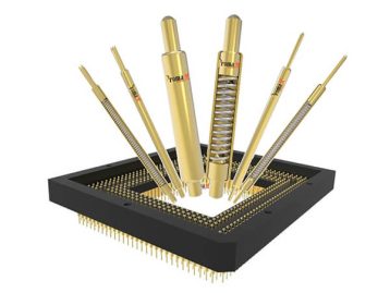
Printed circuit pins form the one of the most important parts of modern circuit board technology, ensuring reliable connections and efficient performance. These pogo pins and PCB board pin connectors play an essential role in linking components placed on the board, transmitting signals, and maintaining the structural integrity of the system. From pcb board pins that secure wiring to pcb on pcb connections enabling multi-layer functionality, they are an indispensable part of the PCB design process. As PCBs have a market size of around $80.33 billion in 2024, according to Mordor Intelligence, printed circuit pins are important now more than ever.
At Promax, we understand that circuit board pins are not just connectors but integral elements adhering to precise design rules outlined in the datasheet. Whether pressed into switches, swaged, or soldered, they provide the necessary conductive pathways for seamless signal flow. For engineers seeking high-quality custom PCB pins, our capabilities as a professional PCB pin manufacturer since 2014 ensure we can meet any design requirements. Additionally, for complex assemblies, explore how a reliable PCB pin connector manufacturer can streamline your project with tailored solutions. Ready to dive deeper into how these small but vital components drive innovation in PCB systems? Keep reading to explore everything engineers need to know!
Key Takeaways
- Printed circuit pins are essential for connecting components and ensuring the structural and functional integrity of PCBs.
- Various types of PCB pins, including header pins, socket pins, and jumper pins, cater to specific design and connectivity requirements.
- PCB connectors, like board-to-board and USB connectors, streamline electrical and signal connections across multiple boards and devices.
- Prototyping and testing connectors enable flexible adjustments without permanent soldering, simplifying circuit debugging and refinement.
- Promax’s high-precision pogo pins offer reliable interconnectivity and optimize efficiency for PCB assembly and design processes.
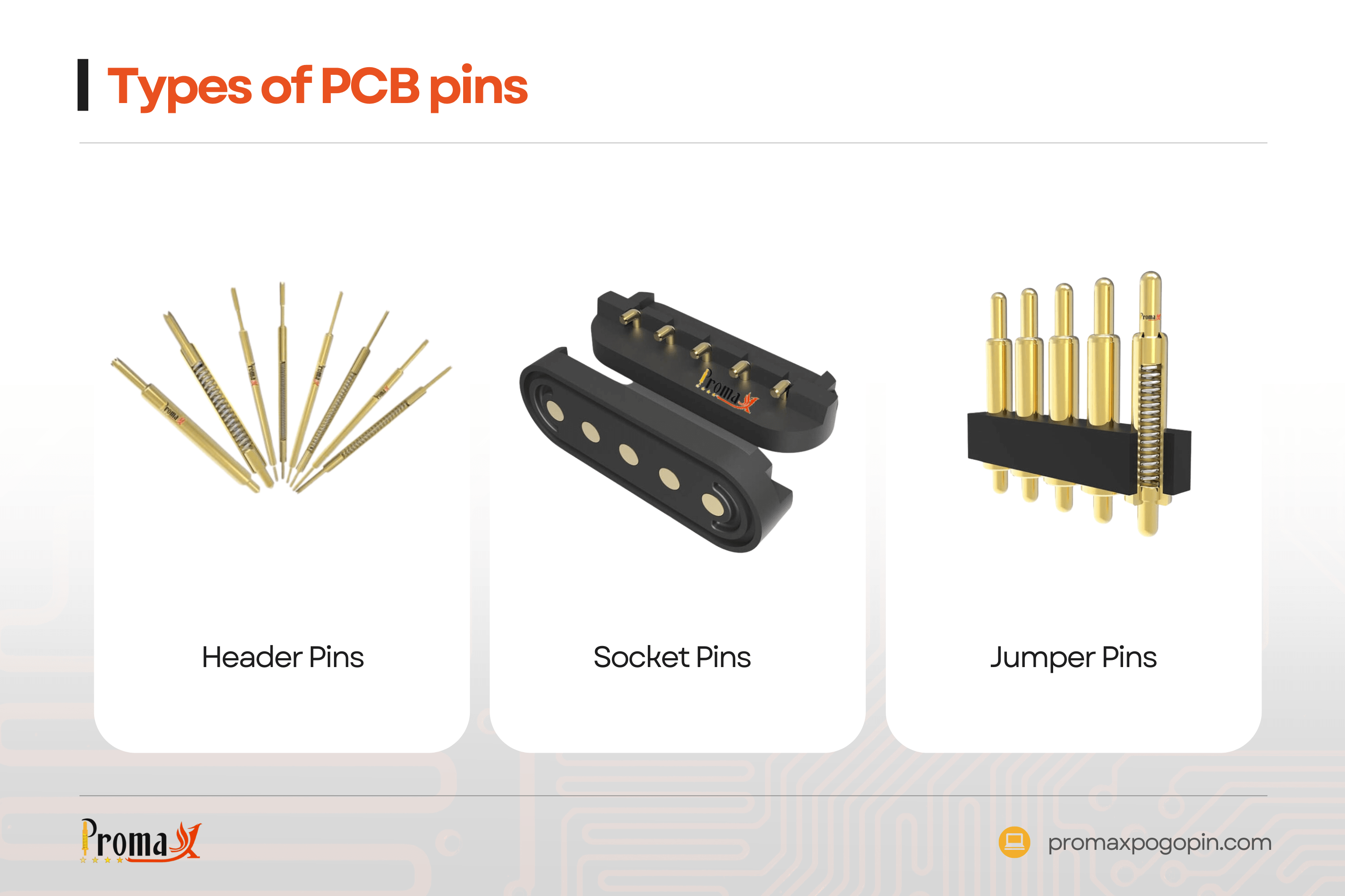
Types of PCB pins
| Type of PCB Pin | Description | Key Features |
|---|---|---|
| Header Pins | Electrically connect components and circuit boards. | Male connectors in rows, various sizes, easy connectivity. |
| Socket Pins | Mount hard-to-place components with standard contact points. |
Variety of sizes, support press-fit and solderless connections. |
| Jumper Pins | Create bypass connections in circuits. | Enable conductive pathways without permanent circuit changes. |
PCB pins make sure there are reliable connections and structural stability in printed circuit board design, and there are quite a few different types. From enabling PCB on PCB connections to supporting intricate layouts where components are placed, these pins are integral to modern electronics. With advancements in PCB design software, engineers can now create precise configurations to align with printed circuit board fabrication needs, supporting everything from ICs to robust copper traces.
Below we break down the common types of PCB pins, each tailored to meet specific requirements in electrical and mechanical connectivity. PCB pins are classified into the following categories:
Header Pins
PCB header pins are often used to connect two components and a circuit board electrically. They can be of many forms and sizes, but they are typically male connections arranged in a row and separated by a predefined distance and range.
PCB Socket Pins
PCB pin sockets are commonly used to mount components that are difficult to place on regular connections or circuit boards. On the circuit board, the PCB pin socket is commonly used to choose characteristics with a standard point of contact. Because of the sizes and variety of PCB pin sockets, consumers can more easily select one or more alternatives according to their requirements. Engineers and designers may now employ press-fit and solderless connectors more easily because of recent advancements in press-fit pin technology.
Compared to older methods, PCB pins remain simple, cut production costs, and improve accessibility. In this case, the designer will have a simpler way of debugging a circuit.PCB alignment and PCB guide pins provide mechanical support for the components on the circuit board. PCB solder pins, on the contrary hand, are one of the most frequently utilized PCB pins when these connectors are assembled to the edge of the PCB board. They are extensively utilized in the fabrication of circuit boards and prototypes.
Jumper Pins for Printed Circuit Boards

Jumper pins are commonly used on printed circuit boards to provide a conduit of conduction through a bypass element of an open or closed electrical circuit. They’re essential because the designer needs to make a bypass connection for the electronic components on the PCB board.
To fulfill the increasing needs of the electronics sector, PCB terminal pins were evolved. The PCB’s terminal pins provide independent, high-current connections. Because of the various types and layouts of PCB pins, the designer can create many installation schemes to support the designs.
Engineers today find it much easier to work on prototypes or finished PCB designs thanks to advancements and improvements made to PCB pins. Due to these innovations, many more complex patterns that appeared impossible to execute using traditional methods are now possible.
Working on a PCB Connector
PCB connectors are essential for establishing electrical connections between parts of a PCB, enabling the seamless transfer of signals or power. These connectors are often integrated into the bare board, leveraging dielectric material like fiberglass to ensure insulation and durability.
Whether it’s creating holes in the board for precise placements or managing routed pathways, connectors are tailored to meet diverse PCB needs. Modern PCB design tools improve flexibility, offering designs that come in a variety of configurations. This design allows for easy integration of the first PCB with other components during or after the manufacturing process.
What Kinds of PCB Connectors Are Most Often Used?
| Type of PCB Connector | Description | Key Features |
|---|---|---|
| Wire-to-Board Connectors | Facilitate connections between a cable and a circuit board. | Provide reliable connections within circuits. |
| Male Pin Headers | A collection of pins with varying spacing used for electrical connections. | Commonly spaced at 0.197, 0.2, or 0.1 inches apart. |
| Board-to-Board Connectors | Connect two PCBs directly without wires, using pins and receptacles. | Enable strong or long-lasting signal connections. |
| Backplane Connectors | Connect multiple PCBs while improving data throughput and signal integrity. | Link boards like daughter boards for complex setups. |
| USB PCB Connectors | Widely used in devices like smartphones, tablets, and cameras for data or power. | Most common type of PCB connector in modern gadgets. |
PCB board cables are required by a wide range of gadgets. As a result, the layout must fit the type, shape, and purpose. This opens up a plethora of PCB connectivity options.
Connectors from Wire to Board
A PCB connector like this one is used to connect a cable to a circuit board. The device facilitates connections within circuits.
PCB Connectors and Male Pin Headers
Pin headers are a collection of pins with varying spacing. Each gap could be 0.197, 0.2, or 0.1 inches apart.
Connectors for Board to Board
Board-to-board connectors allow manufacturers to connect PCBs without the use of a wire. This connector enables a signal connection between two circuit boards. It could be a strong connection that must be “fit and forgotten,” or it could be a long-lasting link. The gadget connects two PCBs through pins and receptacles. Female PCB connectors are sometimes referred to as header receptacles or sockets. It encloses the male connector, allowing power or data signals to pass.
Backplane Connectors
This sort of PCB connector can be connected to many PCBs. It improves data throughput while decreasing signal rise. A backplane connector, a type of support system, can be used to connect another PCB. It also acts as a connector for linking daughter boards, which are framework elements.
USB PCB Connector
This is now regarded to be the most prevalent type of PCB connector. This is hardly unexpected, given how many products we use have USB connectors. Tablets, keyboards, computer mice, smartphones, digital cameras, and other devices are all wonderful examples. There are also many different connector types used for medical devices.
How Can You Test a PCB Connector?
| Type of Testing Connector | Description | Key Features |
|---|---|---|
| Banana Connectors | Create an electric link by wiring a male jack into a female banana plug. | Ideal for integrating components during testing. |
| Alligator Clips | Allow for circuit experimentation by connecting temporary test points. | Useful for testing but prone to accidental short circuits. |
| IC Clips | Hook securely to IC pins without affecting nearby connections. | Excellent for precise troubleshooting and debugging. |
To test a PCB connector effectively, you need to use prototype and testing connectors instead of permanent ones. These temporary connectors allow for adjustments and modifications without soldering or re-soldering PCB components, making the process more flexible during prototyping.
By using this method, you can evaluate different configurations and refine the design as needed. Below are the connector types commonly used for testing purposes. The following connector types are included.
Banana Connectors
“Connectors” are systems that integrate different components of devices. Whenever the male jack is wired into a female banana plug, an electric link is established.
Alligator clips
This type of connector proves ideal for circuit experimentation with various connections while test-running the circuit. However, because they are intended to be utilized only temporarily, you must rely on something other than the reliability of these connectors. As a result, it is frequent to find oneself maybe fumbling with its slick grips and creating accidental short circuits, especially if you manage to contact the nearby metal.
IC clips
This is a stunning interaction that is capable of hooking up to the IC’s pins even without the risk of intimate surrounding pins. Because of this, it is perfect for troubleshooting demands.
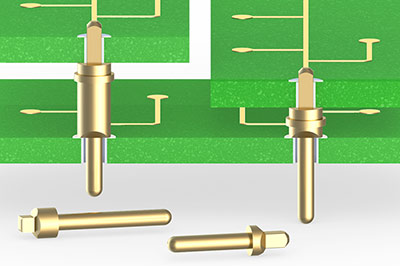
Promax: High Precision Pogo Pins
At Promax, our high-precision pogo pins are designed to be an essential part of the PCB, providing reliable interconnectivity for a wide range of applications. According to PCB Net, approximately 70% of global PCBs are utilized in the consumer electronics, computer, and telecom industries. These components are essential for circuit board design, ensuring seamless connections across the copper layers and enhancing the overall efficiency of the electrical engineering process. From etch detailing to the silkscreen stage, our pogo pins integrate easily into every step of the design process, supporting both SMT and traditional PCB assembly methods.
Whether your project requires high-speed testing, robust electrical components, or the ability to build the board for advanced applications, Promax ensures a solution tailored to your specific needs. For PCB designers seeking precision and durability in high-performance efficient PCB designs, explore our customizable pogo pins today. Contact Promax now to learn how we can optimize your design for success.
Printed Circuit Pins: Everything Engineers Need to Know FAQs
What do you need to be a PCB design engineer?
You need strong knowledge of CAD tools and circuit schematic design. A good understanding of resistor and capacitor functionality is essential for creating efficient boards.
What does a PCB layout engineer do?
A PCB layout engineer arranges board components and traces connections to meet design requirements. They work with PCB manufacturing processes, ensuring designs align with production standards.
Why are circuits important in engineering?
Electronic circuits form the foundation of modern electronic devices, enabling functionality and control. They allow engineers to integrate complex systems like integrated circuits onto a substrate for practical applications.
Back to Top: Printed Circuit Pins: Everything Engineers Need to Know